Preparation
COMfortel 3500 - Firmware Version 1.2B - Commissioning Instructions 02 07/12
43
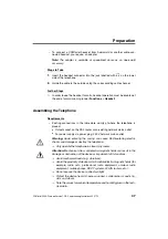
Assembling and Connecting the Key Extension Modules
Requirements
– Up to three key extension modules COMfortel Xtension300
– The mounting hardware accompanying the key extension modules (special
fasteners, screws, and connection cable)
– A screw driver (cross slot)
– Telephone, switched off (disconnected from the 230 V power supply – if
available – and disconnected from the network)
– Telephone and key extension modules, adjusted to the required height
Steps to Take
1.
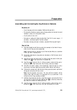
Place the telephone and the key extension modules on the table in the po-
sition in which they are to be assembled.
Note: The key extension modules (up to three are possible) are assembled
at the right side of the telephone.
2.
Rotate the telephone and key extension modules so that the lower side is
in front of you.
3.
Insert the narrower connector (RJ-10) of the connection cable into the jack
labelled with
on the lower side of the telephone.
4.
Insert the wider connector (RJ-11) of the connection cable into the jack la-
belled with
on the lower side of the first key extension module.
5.
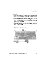
Install the connection cables in the neighboring cable channels in such a
way that you can assemble the special connector without obstructions.
6.
Combine the components with the help of the special connector and fasten
the special connector with two screws.
Note: Only hand-tighten the screws. The key extension modules will be
slightly loose after mounting, to compensate for any unevenness in the
surface on which they are being installed.
7.
Additional key extension modules: Insert the narrower connector (RJ-10) of
the connection cable into the jack labelled with
on the lower side of the
key extension module connected previously.
8.
Insert the wider connector (RJ-11) of the connection cable into the jack la-
belled with
on the lower side of the next key extension module.
Summary of Contents for COMfortel 3500
Page 2: ......
Page 65: ...Stichwortverzeichnis COMfortel 3500 Firmwareversion 1 2B Inbetriebnahmeanleitung 02 07 12 65...
Page 68: ...Beschriftungsschilder 68 COMfortel 3500 Firmwareversion 1 2B Inbetriebnahmeanleitung 02 07 12...
Page 70: ...Lettering Labels 70 COMfortel 3500 Firmware Version 1 2B Commissioning Instructions 02 07 12...
Page 71: ......
Page 72: ......
Page 73: ......
Page 74: ......
Page 75: ......
Page 76: ...884330 02 07 12...

