40
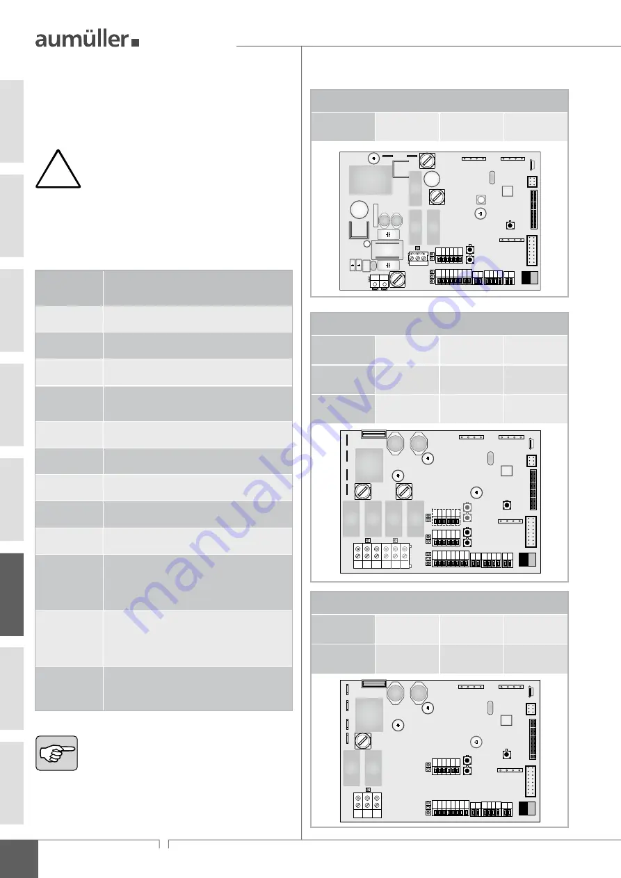
RWA Control Unit
LSF 7000
Control Unit Version
LSF 7000
5A-0102
5 AT
(Battery)
6,3 AT
(Drive 1)
6,3 AT
(Drive 2)
LSF 7000
10A-0102
10 AT
(Battery)
10 AT
(Drive 1)
10 AT
(Drive 2)
LSF 7000
20A-0102
25 AT
(Battery)
10 AT
(Drive 1)
10 AT
(Drive 2)
F1
F1
F1
F2
F2
F2
F3
F3
F3
US
B
1 32 33 35 36 37
1
1
1
22
5
71
1 13 14 15 16 17 18 19
A
S
B
A
Z
A
Z
1 32 33 35 36 37
A
Z
A
Z
Reset
1
1
2
2
3
3
A+
A-
N+
N-
F1
F2
F3
1 72
US
B
Control Unit Version
LSF 7000
5A-0101
5 AT
(Battery)
6,3 AT
(Drives)
LSF 7000
10A-0101
10 AT
(Battery)
10 AT
(Drives)
F1
F1
F2
F2
US
B
1
1
1
22
5
71
1 13 14 15 16 17 18 19
A
S
B
1 2 3
A+
A-
N+
N-
F1
F2
1 72
Reset
1 32 33 35 36 37
A
Z
A
Z
US
B
h
elP
with
m
alfunCtions
or
r
ePair
/ f
uses
h
elp
With
mAlfunctions
or
repAir
All functions and system components important for RWA operation are
permanently monitored for faults. A fault message indicates the type of
fault or, when the central Control Unit is put into operation, any faults in
the connection of system components (e.g. batteries, detectors, drives).
Error /
Fault
Possible causes and
their possible solutions
No indicator
is lit
• No mains power or fuse F1 / F2 is defective
Display „S“ is
flashing
• Check mains power connection
Display „S“ is
flashing quickly
• The batteries are not connected correctly or
are not charging
Display „S“ is
permanently lit
• Line break or
short circuit in the manual fire detection line (HSE)
• Faulty line monitoring
Display „S“ is
blinking slowly
• Line break or short circuit in the smoke detector line
• Faulty line monitoring
Display „S“ is
flashing 2 x
• Maintenance interval reached
(display „B” (green) is lit!)
Display „S“ is
flashing 4 x
• Line break or short circuit in drive line 1
• Faulty line monitoring
Display „S“ is
flashing 5 x
• Only drive line 2,
error cause analogue drive line 1
Display „S“ is
flashing 6 x
• The EMERGENCY CLOSE button (HSE) does not work
correctly or is not recognised
Drives do not
react
• Check fuse F2 / F3
• Check the connection of the drives according to their
assembly instructions
• Or, if the displays (red / green) do not react either:
check ventilation control
Drives are
running
incorrectly
• The displays of the drive direction (red / green) must
correspond to the actual direction. Otherwise replace
the connections on terminals 1 and 2
• Check the connection of the drives according to their
assembly instructions
Signal REL65 is
not recognised
by an external
device
• Check that the REL 65 relay module is correctly
inserted and correctly connected.
The system software allows you to check the system
performance in detail. It is also helpful to have a computer
with the system software ready when contacting our
service department by telephone.
The configuration of the Control Unit via the software
has a significant influence on the functioning of the
individual system components. For this reason, a com-
puter with the system software must be connected for
precise control.
The overview below shows some of the possible faults and problems and
their causes. „Display
B
“ stands for the green operating display which
does not light up in case of a fault. The yellow „Display
S
“ indicates the
type of fault. An overview of all displays can be found in the chapter
„
d
isplays
and
C
ontrols
“.
!
f
uses
Control Unit Version
LSF 7000
2,5A
3,15 AT
(Battery)
3,15 AT
(Drives)
3,15 AT
(primary)
F1
1 32 33 35 36 37
+
+
+
+
-
∼
∼
N L
1
1
1
1
22
5
71
72
1 13 14 15 16 17 18 19
A
S
B
1 2 3
F1
US
B
A
Z
Reset
A
Z
A-
A+
F2
F3
US
B
F2
F3
06
Summary of Contents for Lift-Smoke-Free LSF 7000
Page 54: ...54 RWA Control Unit LSF7000 Notes 08 ...
Page 56: ...9000032001_V0 6_KW50 2021 ...


