14
Assembly Instruction
OFV1
I
nstallatIon
step
4:
r
emOVe
the
hOusing
FrOm
OFV1
and
pLug
in
cOnnectiOn
cabLe
P
reParing
assembly
04
1
1 23
4 5
2 3
4
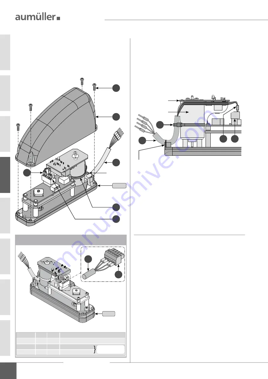
Loosen the screws
and remove the housing
from
the locking drive
OFV1
.
Insert the lock-tight plug
- from the connection
cable
- in the adapter bushing
.
Lay the connection cable
under the circuit board.
Secure connection cables
on motor housing with
supplied cable fastener
.
Cut off protruding end of cable fastener
.
Lead connecting cable
through the housing opening.
1
2
4
3
6
5
housing
opening
5
4
6
3
circuit
board
motor
housing
Housing opening
for connection cable
oFV1
Connection assignment
OFV1
1 2
34
5
oFV1
Terminal
1 BU
= blue
feed line from control unit 24 V DC
Terminal
2 BN
= brown feed line from control unit 24 V DC
Terminal
4
BK
= black to the opening drive
Terminal
5 WH
= white to the opening drive
Note the opening direc-
tion of the casement
1 2 3
4 5
4
3


