15
Assembly Instruction
OFV1
P
reParing
a
ssembly
I
nstallatIon
step
5:
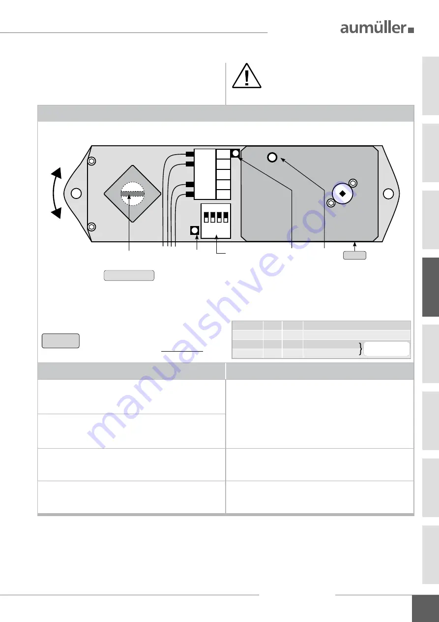
dip
switch
and
Led
dispLay
DIP
switch and
LED
display
DIP
switch
LED
display
1
2
3
4
5
OFF
ON
1 2 3 4
BU
BN
BK
WH
rotating direction
position locked
CLOSE
position
Rotating direction:
right
DIP-
1
=
OFF
DIP-
1
OFF
rotating direction: right (casement DIN left)
ON
rotating direction: left (casement DIN right)
DIP-
2
OFF
angle of rotation 180°
ON
angle of rotation 90°
DIP-
3
OFF
opening drive with direct connection
ON
without opening drive or connection to USKM
DIP-
4
OFF
drives with integrated disconnection (max. 3 A)
ON
drive with
S1
= without disconnection (0,9 A)
Rotating direction:
left
DIP-
1
=
ON
Factory settings
LED-
1
OFF
ready for operation
green
OFV
in operation
green:
blinking
opening drive in operation
red
OFV
fault
red:
blinking
opening drive fault
red/green:
undervoltage (< 19V)
blinking
at
OFV1
(Part.-No.: 513850)
LED-
2
OFF
power supply: none
green
power supply: in
CLOSE
direction
red
power supply: in
OPEN
direction
LED-
3
OFF
OFV
non-operation
green
OFV
left rotation
red
OFV
right rotation
Set the
DIP
switches in a
voltage-free
state.
04
Set the
DIP
switches, when the locking drive
OFV1
is
not mounted.
switch: DIP-
1
DIP-
2
DIP-
3
DIP-
4
LED-
1
LED-
2
LED-
3
oFV1
In case of wrong direction of rotation,
reverse polarity from the opening drive.
n
Ote
Terminal
1 BU
= blue
feed line from control unit 24 V DC
Terminal
2 BN
= brown feed line from control unit 24 V DC
Terminal
4
BK
= black to the opening drive
Terminal
5 WH
= white to the opening drive
Note the opening direc-
tion of the casement


