14
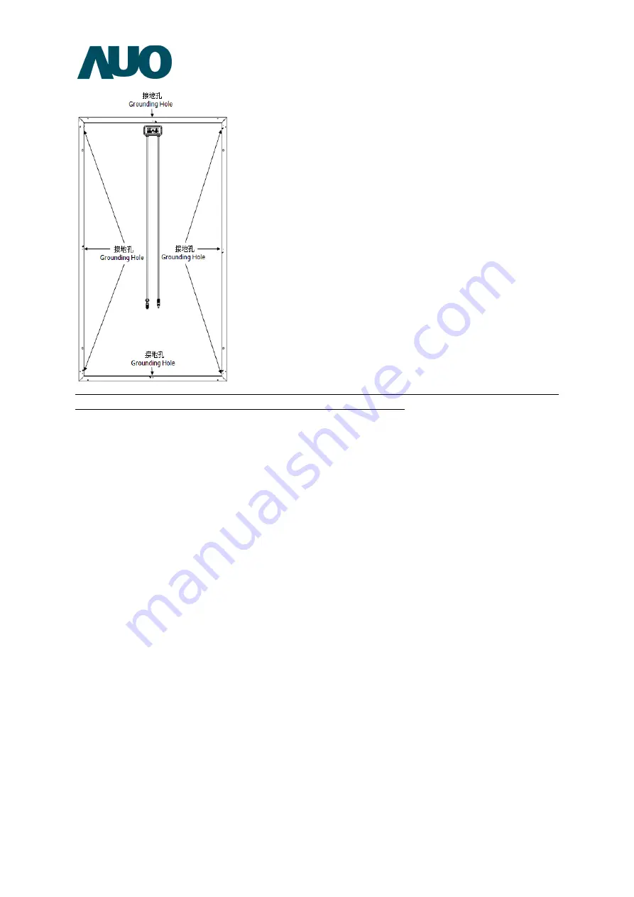
Figure 9: Module Grounding Hole Illustration. Please refer to the corresponding Module Data
Sheet for detailed quantity, size and position of grounding holes.
The components required for grounding the module shall adopt materials that are resistant to
corrosion and ultraviolet and suitable for outdoor use.
Avoid electrochemical corrosion (Galvanic corrosion) caused by contact between the Module
frame and different metals during grounding.
Make sure that the grounding device is electrically connected to the Module frame when
conducting grounding (e.g., if the frame is aluminum alloy, the insulated and anti-corrosion
anodic oxide coating on the aluminum alloy surface must be scrapped off for the grounding
device to allow contact with the internal aluminum alloy in order to provide grounding).
The grounding of the Module can be conducted through the recommended methods as
follows:
3.1.1
3.1.1
3.1.1
3.1.1
Bolted Grounding
Bolted Grounding
Bolted Grounding
Bolted Grounding
Use M4 stainless steel bolts, cup washers, flat washers, star-shaped gaskets, and stainless nuts
to attach the grounding wire onto the Module frame for electrical connection (the
attachment method is illustrated in Figure 10).


