10
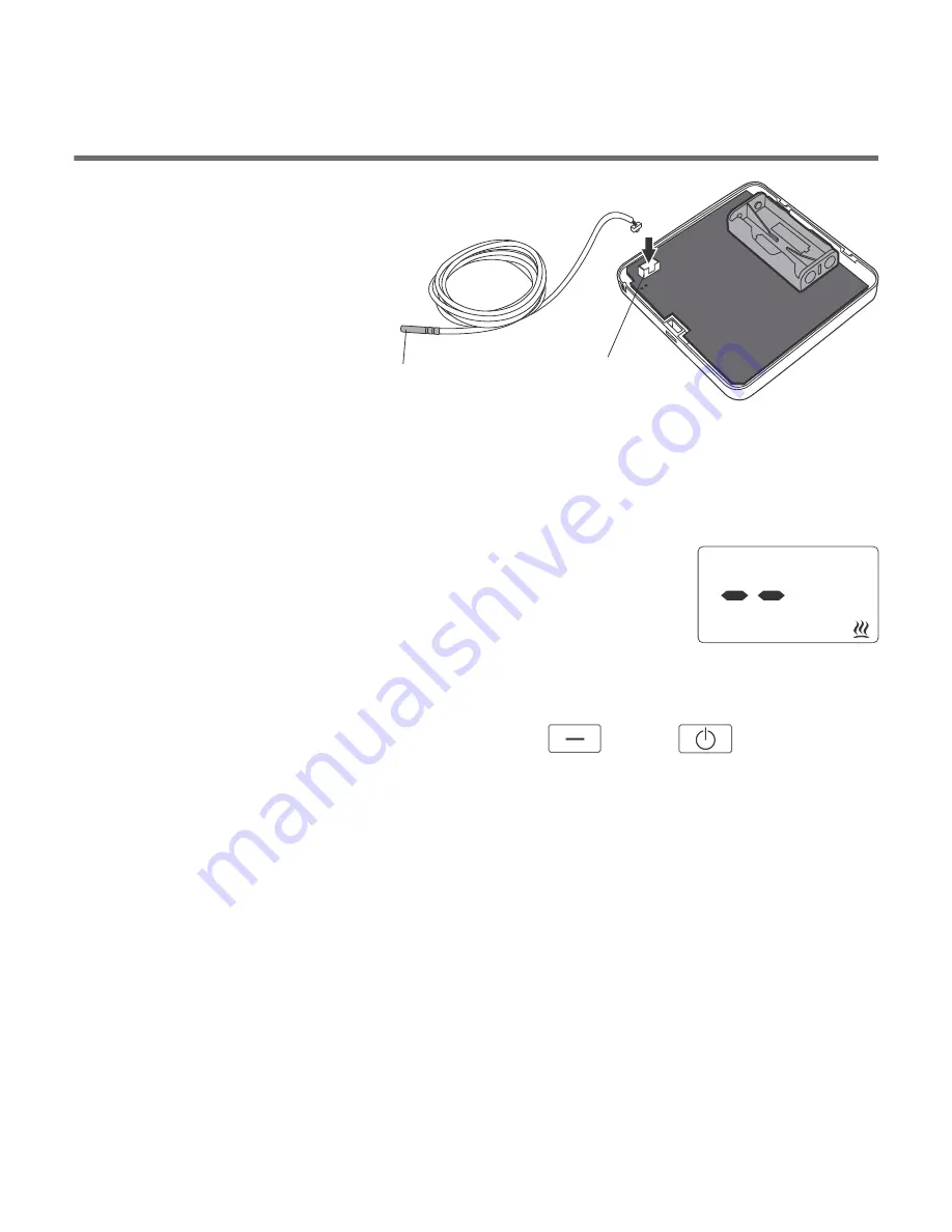
External
temperature
sensor
Terminal
block
External
temperature sensor
As a standard, after the battery is put in, the controller without a sensor
connected displays the temperature from the internal temperature sensor.
When the external temperature sensor is connected, the controller
automatically reads the values measured by that sensor.
If the external sensor is disconnected or defective, the
controller switches into the emergency mode (dashes are
shown as the temperature value) which results in
switching on the relay and, consequently, thecontrolled
device. In order to leave the emergency mode,
the external
temperature sensor must be reconnected or the controller must be restarted
by simultaneously pressing and holding the
and
switches for
at least 5 seconds. After this procedure is completed, the controller displays
the temperature measured by the internal sensor.
[minus]
[power]
Install the sensor on an uncovered outlet pipe connected to the CH boiler (as
close to the boiler as possible). Press the sensor against the tube using a
clamp. It is recommended to wrap the boiler pipe from the boiler to the sensor
with an insulation material.
If a coal-fired boiler and a gas-fired boiler work in the same CH system, the
sensor should be installed in a location where the two outlets merge and
must be insulated.
Mounting the sensor
11
OFF
ON
IN
OUT
ALARM
RESET
Fastening the RTH receiver
cover
NOTE !
When installing the receiver its power
supply must be disconnected. It is
recommended that the installation is
performed by a qualified specialist
.
The permanent electrical system of
a building must include a breaker and
an overcurrent protection.
!
1
. Take off protective covers from the lower
and upper part of the receiver.
2
. Take off
cable tie clamps
from the lower and
upper part of the receiver.
3
. Connect the heating device to the
control
connection terminals
of the receiver.
Proceed in accordance with the service
manual of the heating device. Most
commonly, the
COM
(common) and
NO
(normally open) terminals.
4
. Connect power supply conductors to the
power supply terminals of the receiver,
observing safety rules.
Summary of Contents for S03 RTH
Page 1: ...OFF ON IN OUT ALARM RESET S03 RTH USER S MANUAL EN ...
Page 23: ......
Page 24: ...www auraton pl ver 20180223 ...


