background image


10 

FCC Notice


This  equipment  has  been tested  and found to  comply  with  the  limits for a  Class   
A digital device, pursuant to Part 15 of the Federal Communications Commission 
(FCC) Rules. These limits are designed to provide reasonable protection against 
harmful  interference  in  a  residential  installation.  This  equipment  generates, 
uses, and can radiate radio frequency energy and, if  not  installed and  used in 
accordance  with  the  instructions,  may  cause  harmful  interference  to  radio 
communications.  However,  there  is  no guarantee  that  interference  will  not  occur 
in  a  particular  installation.  If  this  equipment  does  cause  harmful  interference  to 
radio or television reception, which can be determined by turning the equipment 
off  and  on,  the  user  is  encouraged  to  try  to  correct  the  interference  by  one  or 
more of the following measures:


•  Increase the separation between the equipment and the receiver.


•  Connect the equipment into an outlet on a circuit different from that to which 

the receiver is connected.


•  Consult the dealer or an experienced radio or television technician for help.


NOTE:  THE  MANUFACTURER  IS  NOT  RESPONSIBLE  FOR  ANY  RADIO OR 
TV INTERFERENCE CAUSED BY UNAUTHORIZED MODIFICATIONS TO THIS 
DEVICE. SUCH MODIFICATIONS COULD VOID THE USER'S AUTHORITY TO 
OPERATE THE DEVICE.


CE Notice


This  device  complies  with  EMC  Directive 

2004/108/EC  and  2006/95/EC  “Low 

Voltage Directive” issued by the Commission of the European Community.


WEEE Notice


The  WEEE  mark  applies  only  to  countries  within  the  European  Union  (EU)  and 
Norway.


This  appliance  is  labeled  in  accordance  with  European  Directive  2002/96/EC 
concerning  waste  electrical  and  electronic  equipment  (WEEE).  The  Directive 
determines  the  framework  for  the  return  and  recycling  of  used  appliances  as 
applicable  throughout  the  European  Union.  This  label  is  applied  to  various 
products  to  indicate  that  the  product  is  not  to  be  thrown  away,  but  rather 
reclaimed upon end of life per this Directive.


Summary of Contents for ART-04027

Page 1: ...10 USER S MANUAL YUNO K270 I ART 04027 Rev C...

Page 2: ...pment and the receiver Connect the equipment into an outlet on a circuit different from that to which the receiver is connected Consult the dealer or an experienced radio or television technician for...

Page 3: ...nings must not be blocked or covered The openings should never be blocked by placing the product on a bed sofa rug or other similarsurface This product should never be placed near or over a radiator o...

Page 4: ...oduct Overview 3 Specification 4 How to start the module 6 How to Install YUNO board to YUNO K270 7 How to Install or Remove the Mylar 7 Attaching the Side Bracket 8 Side Mounting Instructions 9 Produ...

Page 5: ...2 2 10 Package Overview YUNO K270 BLACK Power Cord DC Power Supply RJ 50 to DB 9M Cable x 2 User Manual Side Bracket Set x 2 Bracket Screws M4 x L8 x 8 pcs Mylar x 8 Thermal Pad Foam Tape...

Page 6: ...3 3 10 Product Overview YUNO K270 is a 27 inch panel PC designed for point of sale and kiosk applications This product is of a modular design enabling easy maintenance Front View Back View...

Page 7: ...x 2 5 7mm SATA MLC SSD Side I O Power button 1 x with Power indicator Blue color when power ON USB 1 x USB 2 0 and 1 x USB 3 0 2 x USB 3 0 Rear Bottom I O DC IN jack 1 x Radio jack connector for 19VDC...

Page 8: ...t Operating Temperature 0 35 C 32 F 95 F Storage Temperature 20 C 60 C 4 F 140 F Humidity 20 80 non condensing Dimension W x D x H LCD 0 degree 385 03 x 64 10 x 644 60mm Weight N W G W 8 04kg 10 55kg...

Page 9: ...How to start the module 1 Remove the cover of module 2 Connect the DC adapter to the power connector on the module 3 Press the Power Switch button to ON OFF the module 4 Add the cover to module Power...

Page 10: ...mounting holes see below 3 To install a cover simply place it on one of the holes 4 To remove a cover use a pointed object to dislodge it Take the thermal pad from accessory box and remove one side o...

Page 11: ...acket B Bracket A Bracket B or Bracket B Bracket A Depending on your mounting scheme alternately you may use the side brackets to mount your displays onto your wall or device Find a suitable location...

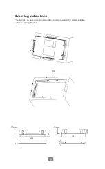
Page 12: ...9 9 10 Mounting Instructions The monitor can be mounted on a wooden or concrete wall with 8 screws and two pairs of opposing brackets OR 1 0 220 0 1 0 186 0 4 1 51 6 20 0 37 4...

Page 13: ...n To download the most recent drivers and utilities and obtain advice regarding the installation of your equipment please visit the AURES Technical Support Website www aures support fr French www aure...

Reviews: