background image


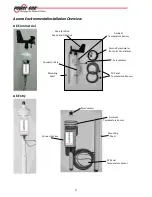
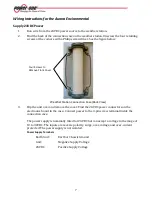
Lining up the two holes in each mast prevents rotation. At this point the entire unit should be secured 

to the support structure. 
It is crucial that the device be oriented as precisely as possible. For the Commercial version, the wind 

direction measurement is directly related to this positioning. 
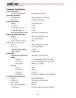
Regardless of how you mount the system, the bottom of the electronic enclosure should not extend 

more than 12” or less than 7” above the support of the mounting tube.   


Other Mounting Considerations 

The exact method of mounting the weather station is left to the installer. However, there are some 

guidelines and recommendations to consider. 


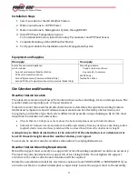
The environmental unit is designed to withstand very harsh weather conditions. Refer to the data for 

individual sensors for the ranges at which measurements remain accurate. 


The environmental unit weighs approximately 7 lbs. Pole mounts in the ground or attached to 

structures that support up to 50 lbs are recommended. 


For ground tripod mounts, the ground should be as level as possible. 


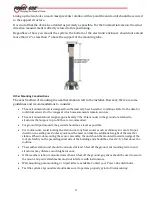
For roof mounts, avoid locating the station near any heat sources such as chimneys or vents. Do not 

install on an existing mast unless you know the mast can take the additional weight of the weather 

station. When roof-mounting the sensor assembly, the unit should be mounted toward an edge of the 

roof preferably on the prevailing wind side of the building and should be at least 2-1/2 feet above the 

roofline.  


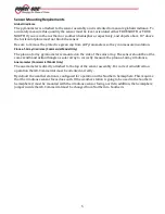
The weather station unit should be mounted at least 5 feet off the ground. Surrounding terrain and 

structures may dictate a much higher mount. 


If the weather station is mounted more than 10 feet off the ground, guy wires should be used to secure 

the mount. Guy wire attachments must not interfere with instruments. 


Wall-mounting, pole-mounting, or tripod kits are available. Contact your Power-One distributor. 


Test the system at ground level and make sure it operates properly prior to final mounting. 

Summary of Contents for VSN-ENVIRO-CMML

Page 1: ...THE MANUAL AURORA ENVIRONMENTAL Model Number VSN ENVIRO ENTRY VSN ENVIRO CMML...

Page 2: ...omparison to predicted environmental data and actual inverter solar panel output The RS485 port of the Aurora Environmental Appliance is attached via low voltage wires to the monitoring or management...

Page 3: ...Pyranometer Ambient Temperature Sensor Connector Case PV Panel Temperature Sensors Second Pyranometer For Solar Panel Plane Vane for Wind Speed and Direction Mounting Mast Pyranometer Mounting Mast Co...

Page 4: ...n Ambient air temperature and irradiance measurements can be affected by obstructions local topography and surface type Each site is different and presents unique challenges By far the most important...

Page 5: ...mounts in the ground or attached to structures that support up to 50 lbs are recommended For ground tripod mounts the ground should be as level as possible For roof mounts avoid locating the station n...

Page 6: ...array pyranometer is mounted on the side of the solar array The sensor should be at the same zenith and azimuth angle as solar array to correctly measure the plane of array irradiance Anemometer Comm...

Page 7: ...g element Run the cable back to the weather station unit and connect to the PV temperature sensor terminals If the cable length is insufficient for the installation additional cable can be added to th...

Page 8: ...lip the unit over and remove the cover Find the 24VDC power connectors on the electronics board in the case Connect power to the 3 pin screw terminal inside the connection case The power supply is nom...

Page 9: ...tion and the management system to complete the physical connection The connection to the management system can be as a single RS485 device or as part of a daisy chain of RS485 devices Cable is not sup...

Page 10: ...5 Attach the second Pyranometer to your array The sensor should be attached so top of the sensor is in the same plane as the PV panels The sensor comes pre attached to a bracket for easy installation...

Page 11: ...rminal 1st Sensor PV Temp 1 Signal Black or White PV Temp 1 Signal Black or White Shield Cable Shield and Drain bare PV Temperature Terminals 2nd Sensor PV Temp 2 Signal Black or White PV Temp 2 Signa...

Page 12: ...Shield Cable Shield and Drain bare Complete the Installation 1 Properly ground the weather station by connecting the Earth GND terminal at the Weather Station to an earth ground Connecting the Earth...

Page 13: ...ires for the 24VDC power and RS485 to the Aurora Universal See the figure below Note that some Aurora Universal models may have RS485 connection points in other locations Weather Station Connection to...

Page 14: ...in Hardware Stainless Steel and Nylon Locknut Foam Gasket Vinyl and Acrylic Enclosure RoHS Compliant IP65 Rated Outdoor Enclosures UL 94 V 2 Polycarbonate Body Pyranometer Sensor RoHS Compliant Body A...

Page 15: ...Time Constant 30 sec PV Panel Temperature Sensors Range 40 to 80C 40 to 176 F Accuracy 0 3 C 0 54 F Thermal Time Constant 270 sec Cable Length 7 62m 25 ft Anemometer Operational Temperature 40 to 60 C...

Page 16: ...omer Support E mail service us power one com www power one com 2011 2012 Power One Corporation Power One is a registered trademark and Aurora Vision is a trademark of Power One Corporation All rights...

Page 17: ...800 00 28 76 72 Aurora Power Service Germany 0800 2200211 Aurora Power Service Italy 00 800 00 28 76 72 Aurora Power Service Spain 00 800 00 28 76 72 Aurora Power Service Middle East 00 800 00 28 76...

Reviews: