8
Commercial
Entry
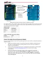
Weather Station Electronics Board
4.
Leave the case open to install the other wires as described in the next section.
Southern Hemisphere Adjustment
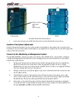
For the Commercial model, if you are in the southern hemisphere, the jumper at J11 must be set to
Southern. If you are in the northern hemisphere, no adjustment is required. J11 is located in upper left
section of the circuit board.
Connect to the Monitoring or Management System
The ModBus (RS485) connection is same as with any other RS485 device connected to a SunSpec-
compliant management system. Refer to your management system documentation of any unique
installation requirements.
1.
String cable between the weather station and the management system to complete the
physical connection. The connection to the management system can be as a single
RS485 device or as part of a daisy chain of RS485 devices. Cable is not supplied with the
unit. Use twisted pair wire for connections.
2.
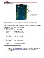
Wiring connections are made using the 3-pin screw terminal inside the connection case.
See the figure below.
3.
The RS485 line must be terminated with a 120-ohm resistor. If the device is the only
device in the chain or at the end of the chain, you must set the jumper (J8) to terminate
the RS485 line. The factory setting for RS485 line termination is OFF.
4.
Placement can be other than the end of the chain if the RS485 termination is disabled.
To locate the device in the middle of a daisy chain, set the jumper at location J8 between
the pins
Common
and
Off
to disable RS485 termination.
24VDC Connectors:
Earth GND
GND
24VDC Power

