n
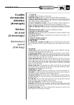
Composants
1- Contacteur à clef.
Démarrage et arrêt du moteur.
2- Interrupteur éclairage.
Indique le correct fonctionnement du tableau commandaments.
3- Témoin de pression d'huile du moteur.
Celui-ci s'allumera si le niveau d'huile dans le carter
est insuffisant. Si le témoin s'allume alors que le moteur est en marche, arrêtez immédiatement le
moteur. Vérifiez la pression et le niveau de l'huile.
4- Témoin de température du moteur.
Lorsque celui-ci s'allume, arrêtez inmédiatement le
moteur et cherchez la cause de ce subit allumage du témoin de température du moteur.
5- Témoin de charge de batterie.
Il s'allume avec le contact lorsque l'alternateur ne charge pas
la batterie et il s'éteint lorsque le régime du moteur est plus important que le régime du moteur au
ralenti.
6- Interrupteur d' avertisseur sonore.
En poussant sur l'interrupteur vous klaxonnez.
7- Interrupteur pour giro-phare (en option).
8- Horamètre.
Indique le nombre d'heures de fonctionement de la machine et permet de contrô-
ler la périodicité des révisions.
9- The indicator of amber colour,
is illuminated when we work the key of the switch 1 in the
warm-up position " B ".
10- Témoin de saturation du filtre à air.
11- Indicateur réserve combustible.
12- Boîte à fusibles.
13- L'indicateur de la sélection de la vitesse,
le feu vert est éclairé quand la vitesse sélec-
tionnée est la rapide et la lumière orange est éclairée quand la vitesse sélectionnée est le lente -
ment un.
n
Components
1- Starter switch.
Insert the key and turn this switch clockwise until pre-heat lamp (9) glows oran-
ge. Turning this switch fully clockwise will start the engine.
2- Instrument panel lighting.
This lamp glows when the instrument panel is working correctly.
3- Oil pressure lamp.
When this lamp is lit it means that the engine oil level is low causing low
oil pressure to the engine. The engine should be stopped immediately to prevent engine dama-
ge. Add oil to the engine until the proper level is reached.
4- Engine temperature lamp.
This gauge shows the temperature of the coolant in the engine
cooling system. When this lamp glows it means that the engine is operating at a high temperatu-
re which could damage the engine. The engine should be stopped immediately to determine the
cause of the high temperature. It could be low coolante, debris in the radiator or a thermostat
which does not operate correctly.
5- Battery charge lamp.
This gauge shows the condition of the battery. Once the engine starts
to run this lamp will go out indicating that the alternator is charging properly. If this lamp remains
lit stop the engine immediately and determine the cause.
6- Horn button.
Push to activate.
7- Rotating beacon switch.
To switch on, push the lever down; to switch off, push the lever up.
8- Hourmeter.
This gauge indicates the total running time of the dumper engine to enable servi-
cing at proper intervals. (See Maintenance chart for servicing frequency).
9- Engine pre-heat lamp.
When this lamp glows it indicates that the engine pre-heat plugs are
in operation and heating the combustion chamber to a temperature that will enable firing of the
vaporized diesel fuel.
10- Air filter lamp.
When the air filter of the diesel engine becomes clogged with dirt, this lamp
will light. The air filter should be immediately cleaned or serviced.
11- Low fuel warning lamp.
This light is lit when diesel fuel level nears empty.
12- Fuse box.
The fuse box has places for 5 fuses. The number of fuses depends on the electri-
cal equipment of each machine. See the Electrical Diagram at the rear of this Manual to identify
the number and function of each fuse.
13- Speed selection lamp.
Green lamp will light when fast driving speed is selected. Orange
lamp will light when slow driving speed is selected.
250-300-350-400 AH/AHG
19
Cuadro
de mandos
eléctrico
(Arranque)
Tableau
de bord
(Démarrage)
Instrument
panel
(Starting)
Summary of Contents for 250 AH
Page 1: ...250 300 350 400 AH 250 300 350 400 AHG ...
Page 2: ...2 250 300 350 400 AH AHG ...
Page 4: ...4 250 300 350 400 AH AHG ...
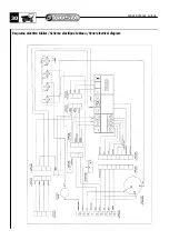
Page 28: ...28 250 300 350 400 AH AHG Esquema eléctrico Schéma eléctrique Electrical diagram Schaltpläne ...
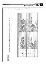
Page 29: ...250 300 350 400 AH AHG 29 Esquema eléctrico Schéma eléctrique Electrical diagram Schaltpläne ...
Page 31: ...Esquema eléctrico Schéma eléctrique Electrical diagram 250 300 350 400 AH AHG 31 ...
Page 32: ......


