Parking
brake
Oil: Replacing
If the brake pedal lowers excessively, refer to the authorized AUSA dealer for adjusting,
bleeding or replacement of the inner discs.
Releasing the parking brake while the engine is stopped:
- This operation should be carried out following the instructions given in
“Towing
the forklift”
in this Operator’s and Safety Manual.
Service
brake
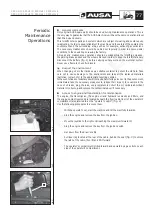
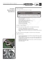
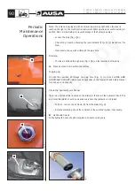
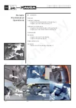
Adjusting (fig. 1)
If the pedal has excessive free play, this can be corrected using the push rod
(a)
of the
pedal which operates the brake pump. This has a system of nut and locknut. Allow the
push rod to have a free play of between 0’04 and 0’06 in., making sure that the pump is
free of internal pressure.
If, on applying the service brake, the pedal lowers too much it should be adjusted. To do
so, contact an AUSA authorized dealer.
To replace the brake discs contact an authorized AUSA dealer.
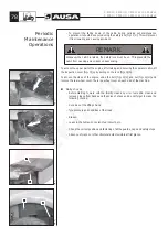
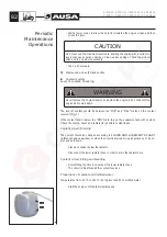
Chek that, when the brakes are released (pressure inserted), levers
(19)
do lean against
the screws
(18)
without prestressing them and make sure that a clearance
(b)
is left
between cylinder
(4)
an d lever
(19)
. Also check that when pressure is released, piston
(13)
projects out by 0’16 ÷ 0’19 in (4 ÷ 5 mm)
(fig. 2)
.
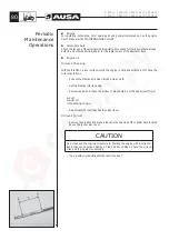
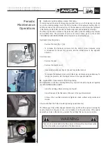
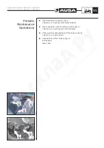
Brake and inching fluid: Checking the level
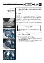
With the forklift parked on a level surface, the level of the brake fluid in the tank should
lie between the marks MIN. and MAX.
(fig. 3)
.
If necessary, top up the brake fluid in the tank:
- Unscrew the filler cap and use a funnel to prevent spillage.
- Top up with fluid until the level reaches the MAX. mark.
- Close the filler cap by screwing it on again.
Note:
While topping up, do not exceed the MAX. mark.
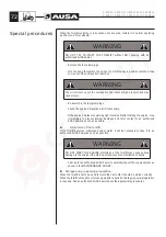
WARNING
If it becomes necessary to top up the brake fluid frequently, it is possible that the
brake system has a leak. Park the forklift correctly (See the section
PARKING
THE FORKLIFT TRUCK
) and consult an authorized AUSA dealer.
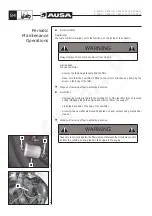
Brake an inching fluid: Replacing
The replacement of brake fluid or any repair to the brake system should be carried out
by an authorized AUSA dealer.
(fig. 1)
a
(fig. 3)
MÁX
MÍN
(fig. 2)
5
4
13
19
18
b
C 400 H / C 400 HI / C 400 H x4 / C 400 HI x4
C 500 H / C 500 HI / C 500 H x4 / C 500 HI x4
86
Periodic
Maintenance
Operations

