D201RH / RHS / RHG / RHGS
45
Periodic
Maintenance
Operations
(fi
g.
2)
(fi
g.
1)
MAX
MAX
MIN
MIN
(fi
g.
3)
Cooling system
Level of coolant: Checking
WARNING
Never remove the expansion tank cap while the engine is hot. Wait until the
engine is cold
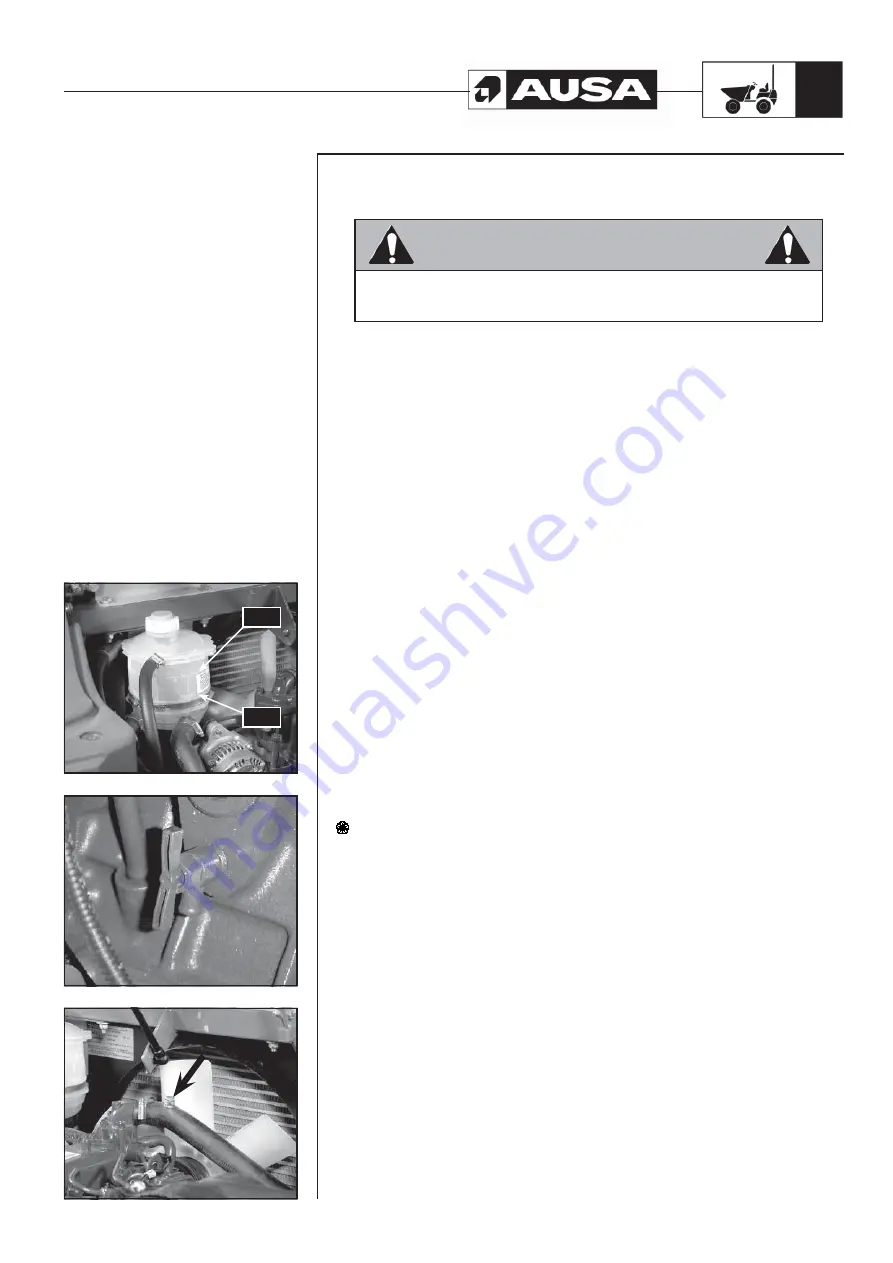
The level of coolant should be between the “MIN” and “MÁX” marks on the reservoir
(fig. 1)
If the coolant level is below the “MIN” mark, top up the reservoir with coolant. Check the
engine, hoses and radiator for possible coolant leaks.
Coolant circuit: Draining
The coolant should be changed according to Table of
LIQUIDS AND LUBRICANTS
(references and capacities), or when the circuit is drained for repair purposes. To do so,
proceed as follows:
- Place a container below the radiator.
- Disconnect the lower radiator hose in order to drain the radiator through this
point.
- Open the drainage cock located on the left-hand side of the engine to drain the
coolant
(fig. 2)
.
Coolant circuit: Filling and bleeding
- Before filling the circuit, re-connect the lower radiator hose.
- Close the engine drainage cock.
- The circuit is filled through the coolant reservoir.
Proportions of coolant and distilled water:
Temperatures from -17 ºC to 127 (1,4ºF to 260ºF): 30 % glycol and 70 % distilled water.
Temperatures from -35 ºC to 145 ºC (-31ºF to 293ºF): 50 % glycol and 50 % distilled
water.
- Start the engine until the thermostat opens.
- Then, when the engine is cold, check the level of coolant in the reservoir
- If necessary, bleed the coolant circuit using the bleeder located on the radiator
hose
(fig. 3)
.
Dispose of used coolant in authorized waste disposal centres.
Summary of Contents for D 201 RH
Page 1: ...D 201 RH D 201 RHS D 201 RHG D 201 RHGS OPERATOR S MANUAL ENGLISH Original Manual ...
Page 2: ......
Page 3: ...D 201 RH D 201 RHS D 201 RHG D 201 RHGS Original Manual Above chassis number 62439 ...
Page 4: ......
Page 66: ...D201RH RHS RHG RHGS 64 Electric Diagram H1 ...
Page 67: ...D201RH RHS RHG RHGS 65 Electric Diagram H2 ...
Page 68: ...D201RH RHS RHG RHGS 66 Electric Diagram H3 ...
Page 69: ...D201RH RHS RHG RHGS 67 Electric Diagram H4 ...
Page 72: ...D201RH RHS RHG RHGS 70 D 201 RH hydraulic diagram ...
Page 73: ...D201RH RHS RHG RHGS 71 D 201 RHS hydraulic diagram ...
Page 74: ...D201RH RHS RHG RHGS 72 D 201 RHG hydraulic diagram ...
Page 75: ...D201RH RHS RHG RHGS 73 D 201 RHGS hydraulic diagram ...
Page 76: ...D201RH RHS RHG RHGS 74 Transmission hydraulic diagram ...
Page 78: ......
Page 79: ......
Page 80: ......


