D201RH / RHS / RHG / RHGS
48
Periodic
Maintenance
Operations
(fi
g.
3)
(fi
g.
1)
(fi
g.
4)
a
b
(fi
g.
2)
1mm
(0,03 in)
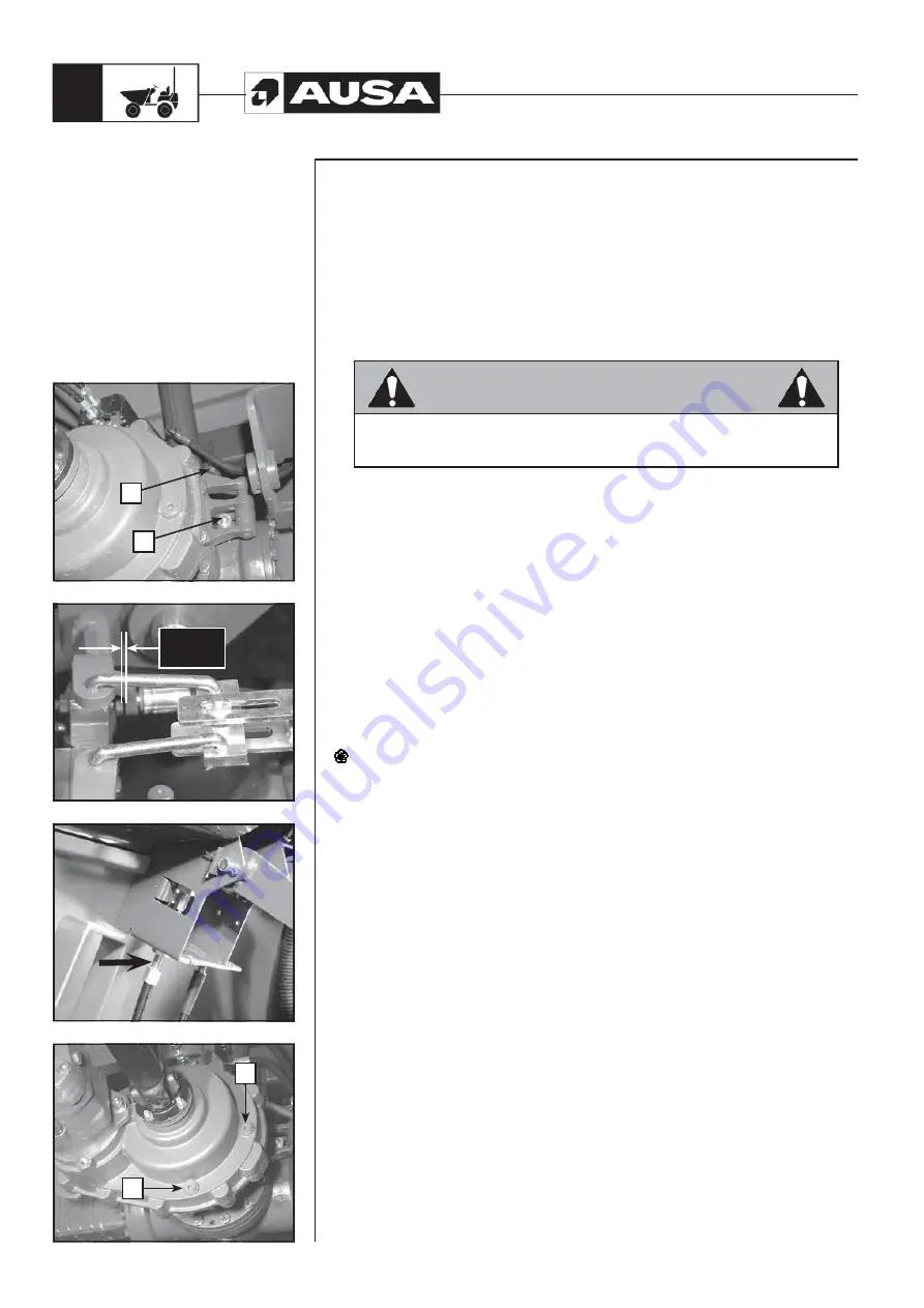
Service brake (fig. 1, 2, 3)
If, when the service brake pedal is depressed it lowers too far, it should be tightened.
- Place the parking brake lever in released position.
- Tighten the nuts
(a)
on both sides of the axle until the pedal reaches the required
feeling.
- Adjust the lever stops
(b)
on both sides of the axle allowing a clearance between
the lever and the stop of 1 mm. (0,03 in.)
Note:
The cable sheath may also be tight on the pedal support
WARNING
The brake pedal should have a clearance of about 1 to 1’5 mm (0,03 to 0,05
in.) The cables should be free of tension.
To replace the brake discs contact an authorized AUSA dealer.
Oil for TRANSFER BOX “COMPEN SYSTEM” (fig. 4).
Checking the level
- To check the oil level unscrew the cap
(a)
. The oil should be at the level of the
housing.
Draining
To drain the oil, unscrew the plug
(b)
located on the lower part.
Topping up
- Fill in with the specified oil through the opening of the plug
(a)
. See the Table of
LIQUIDS AND LUBRICANTS
(references and capacities) in this Manual for oil
type and capacity.
Dispose of used oil in authorized waste disposal centres.
a
b
Summary of Contents for D 201 RH
Page 1: ...D 201 RH D 201 RHS D 201 RHG D 201 RHGS OPERATOR S MANUAL ENGLISH Original Manual ...
Page 2: ......
Page 3: ...D 201 RH D 201 RHS D 201 RHG D 201 RHGS Original Manual Above chassis number 62439 ...
Page 4: ......
Page 66: ...D201RH RHS RHG RHGS 64 Electric Diagram H1 ...
Page 67: ...D201RH RHS RHG RHGS 65 Electric Diagram H2 ...
Page 68: ...D201RH RHS RHG RHGS 66 Electric Diagram H3 ...
Page 69: ...D201RH RHS RHG RHGS 67 Electric Diagram H4 ...
Page 72: ...D201RH RHS RHG RHGS 70 D 201 RH hydraulic diagram ...
Page 73: ...D201RH RHS RHG RHGS 71 D 201 RHS hydraulic diagram ...
Page 74: ...D201RH RHS RHG RHGS 72 D 201 RHG hydraulic diagram ...
Page 75: ...D201RH RHS RHG RHGS 73 D 201 RHGS hydraulic diagram ...
Page 76: ...D201RH RHS RHG RHGS 74 Transmission hydraulic diagram ...
Page 78: ......
Page 79: ......
Page 80: ......


