Section 03
ENGINE
Subsection 12
(CVT)
VMR2004_135_03_12A.FM
03-12-3
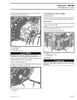
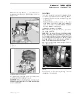
Screw tool in the threaded hole of driven pulley
and tighten to open the pulley.
1. Driven pulley expander
2. Fixed half of driven pulley
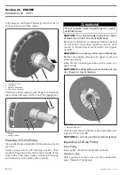
To remove belt
no. 4
, slip the belt over the top edge
of sliding half, as shown.
1. Screw in of driven pulley expander
2. Removal direction for belt
Inspection
Inspect belt for cracks, fraying or abnormal wear.
Replace if necessary.
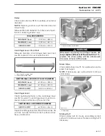
Check drive belt width. Replace if it is out of spec-
ification (see table below).
1. Drive belt
A. Belt width
Installation
For installation, reverse the removal procedure.
Pay attention to following details.
The maximum drive belt life span is obtained when
the drive belt has the proper rotation direction. In-
stall it so the arrow printed on belt is pointing to-
wards the back of the vehicle.
NOTE:
Put a small amount of Loctite 5910 in the
groove of CVT cover to ease installation of CVT
cover with gasket
no. 3
.
Install the center top screw of cover in first.
Install the other screws then torque them in a criss-
cross sequence.
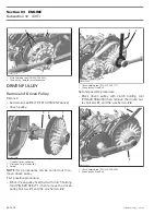
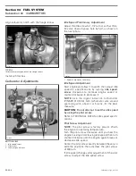
DRIVE PULLEY
1. Belt
2. Drive pulley
3. Driven pulley
DRIVE BELT WIDTH
NEW NOMINAL
32.00 mm (1.260 in)
SERVICE LIMIT
30.00 mm (1.181 in)
R400motr156A
1
2
2
R400motr157A
1
1
R400motr158A
A
1
R400motr159A
2
3

