Section 03
ENGINE
Subsection 12
(CVT)
03-12-4
VMR2004_135_03_12A.FM
Removal of Drive Pulley
Remove belt
no. 4
.
NOTE:
To remove drive pulley, two procedures can
be followed.
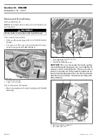
First possible procedure:
– Remove the spark plug (refer to CYLINDER AND
HEAD).
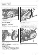
– Put piston at TDC and lock crankshaft with crank-
shaft locking bolt (P/N 529 035 617).
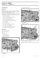
1. Crankshaft locking bolt
2. Output shaft (front side)
Second possible procedure:
– Block drive pulley with clutch holding tool (P/N 529
006 400).
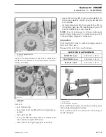
1. Clutch holding tool (P/N 529 006 400)
2. Drive pulley sliding half
3. Area to place holding tool hook
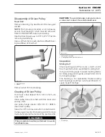
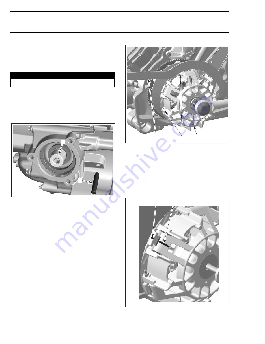
CAUTION:
Prior to removing the drive pulley,
mark sliding half and governor cup together to
ensure correct reinstallation. There are only 4
levers mounted out of 6 possible positions for
the Outlander 400 execution. On the Outlander
330, there are 3 levers mounted out of 6 possi-
ble positions.
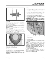
1. Mark on drive pulley sliding half
2. Mark on governor cup
WARNING
Drive pulley screw has a left-hand thread.
R400motr236A
1
2
2
R400motr161A
3
1
2
R400motr164A
1

