Section 03
ENGINE
Subsection 12
(CVT)
VMR2004_135_03_12A.FM
03-12-7
Roller
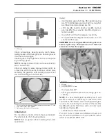
Check each roller
no. 19
for roundness of external
diameter.
NOTE:
Replace governor cup if the roller does not
move freely.
Measure the roller diameter. If a roller is out of spec-
ification, replace governor cup.
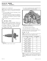
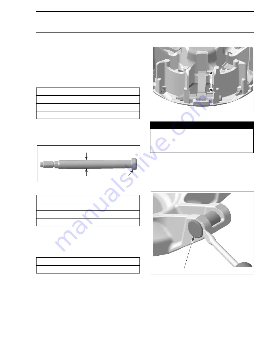
Centrifugal Lever Pivot Bolt
Measure diameter of centrifugal lever pivot bolt
no. 13
, replace if it is out of specification.
1. Centrifugal lever pivot bolt
A. Measure diameter here
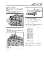
Centrifugal Lever
Check bushing diameter in the centrifugal lever
no. 14
for wear. If a centrifugal lever must be re-
placed, replace all levers at the same time.
Replace centrifugal lever
no. 14
with screws
no. 13
and lock nuts
no. 12
if the contact surfaces show
heavy visible wear.
1. Contact surface to the roller
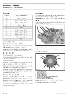
Slider Shoe
Check slider shoes
no. 11
for visible wear and re-
place if damaged.
NOTE:
If necessary, use a screwdriver to remove
slider shoes.
1. Slider shoe
Sliding Half
Check sliding half for cracks and sliding contact
surface for excessive wear. Replace sliding half if
necessary.
ROLLER DIAMETER
MINIMUM (new)
13.70 mm (.539 in)
MAXIMUM (new)
13.90 mm (.547 in)
SERVICE LIMIT
13.20 mm (.519 in)
CENTRIFUGAL LEVER PIVOT BOLT DIAMETER
MINIMUM (new)
6.078 mm (.239 in)
MAXIMUM (new)
6.100 mm (.240 in)
SERVICE LIMIT
6.00 mm (.236 in)
CENTRIFUGAL LEVER BORE DIAMETER
SERVICE LIMIT
6.200 mm (.244 in)
1
A
R400motr169A
WARNING
Whenever replacing centrifugal levers,
al-
ways replace all levers at the same time
. Oth-
erwise, the drive pulley will be unbalanced
(because of lever differences).
R400motr170A
1
1
R400motr171A

