Section 03
ENGINE
Subsection 12
(CVT)
03-12-14
VMR2004_135_03_12A.FM
Installation of Driven Pulley
For installation, reverse the removal procedure.
Pay attention to the following details.
Install sliding half
no. 30
into fixed half
no. 31
.
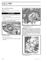
Place O-ring
no. 34
on main shaft splines and
move it with spacer
no.
35 in end position.
CAUTION:
Chamfer on inside diameter of the
spacer must face engine side.
1. O-ring
2. Distance sleeve
3. Chamfered area of distance sleeve
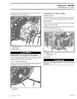
Install cam retainer
no. 32
on main shaft end the
right way then install cam
no. 29
.
NOTE:
Place cam retainer
no. 32
with printed
mark ENGINE SIDE towards the engine.
1. Sharp edge of cam retainer to engine side
2. Main shaft spline
3. Inscription
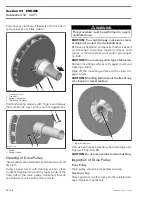
Place spring
no. 33
behind sliding half then align
driven pulley with cam.
1. Cam
2. Spring
3. Driven pulley
4. Location for pushing during screw installation
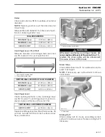
Push the driven pulley by hand. Install the driven
pulley screw
no. 21
and washer
no. 22
.
CAUTION:
Always place washer
no. 22
at the
time of driven pulley installation.
1. Washer
2. Driven pulley screw
NOTE:
Driven pulley end-play is 0 (zero).
Torque driven pulley screw.
3
R400motr190A
1
2
2
R400motr191A
1
3
WARNING
Driven pulley is a spring loaded system.
1
R400motr192A
2
4
3
2
R400motr193A
1


