Section 03
ENGINE
Subsection 05
(COOLING SYSTEM)
03-05-10
VMR2004_128_03_05A.FM
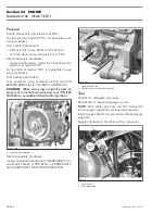
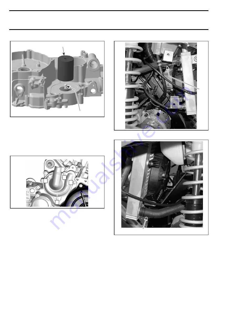
1. Water pump shaft with rotary seal
2. Water pump ceramic seal installer (P/N 529 035 766)
NOTE:
For installation use the torque values in the
exploded view. Ensure to use multi-purpose grease
for oil seal
no. 10
and engine oil in water pump
shaft bore/shaft.
Tighten screws in the following sequence.
PRESSURE CAP
Check if radiator cap
no. 11
pressurizes the sys-
tem. If not, install a new 110 kPa (16 PSI) cap (do
not exceed this pressure).
RADIATOR
Removal
Drain cooling system.
Remove:
– front facia and both inner fenders (refer to BODY)
– radiator inlet
no. 14
and radiator outlet
no. 16
hoses
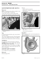
1. Radiator inlet hose
1. Radiator outlet hose
– overflow hose
no. 12
– mounting bolts
no. 17
.
1
2
R400motr148A
4
R400motr231B
2
3
1
1
V07C0PA
1
V07C0QA


