Section 03
ENGINE
Subsection 09
(CYLINDER AND HEAD)
VMR2004_132_03_09A.FM
03-09-9
CAUTION:
Crankshaft and camshaft must be
locked on TDC position to place camshaft timing
gear and timing chain in the proper position.
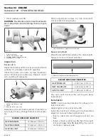
Double-check position of timing gear with cam-
shaft locking tool (P/N 529 035 926)
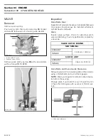
1. Camshaft locking tool
2. Camshaft screw
3. Camshaft timing gear
When the camshaft timing gear and the timing
chain are installed, remove the crankshaft locking
bolt as well as the camshaft locking tool.
Reinstall all other removed parts.
ROCKER ARM
Removal
Lock crankshaft at the TDC compression position,
refer to CRANKSHAFT/BALANCER SHAFT, see
CRANKSHAFT LOCKING PROCEDURE.
Remove:
– valve cover
– chain tensioner
– camshaft timing gear
no. 10
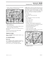
– Allen screws
no. 25
and camshaft retaining plate
no. 26
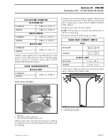
1. Cylinder head
2. Allen screws
3. Camshaft retaining plate
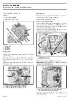
– rocker arm shafts
no. 11
– rocker arm assembly (exhaust side
no. 12
and
intake side
no. 15
) with adjustment screws
no. 14
and nuts
no. 13
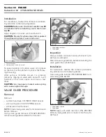
1. Rocker arm shaft
2. Rocker arm (exhaust side)
3. Rocker arm (intake side)
4. Adjusting screw
5. Locking nut
2
R400motr62A
3
1
1
R400motr65A
2
3
3
R400motr66A
2
1
4
5


