Section 03
ENGINE
Subsection 10
(CRANKSHAFT/BALANCER SHAFT)
VMR2004_133_03_10A.FM
03-10-3
GENERAL
During assembly/installation, use the torque values
and service products as in the exploded views.
Clean threads before applying a threadlocker. Re-
fer to SELF-LOCKING FASTENERS and LOCTITE
APPLICATION at the beginning of this manual for
complete procedure.
CRANKSHAFT LOCKING
PROCEDURE
Removal
Unplug spark plug cable then remove the spark plug.
Remove valve cover (refer to CYLINDER AND HEAD).
To place piston at TDC, pull rewind starter to rotate
crankshaft until piston is at TDC compression po-
sition.
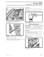
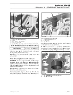
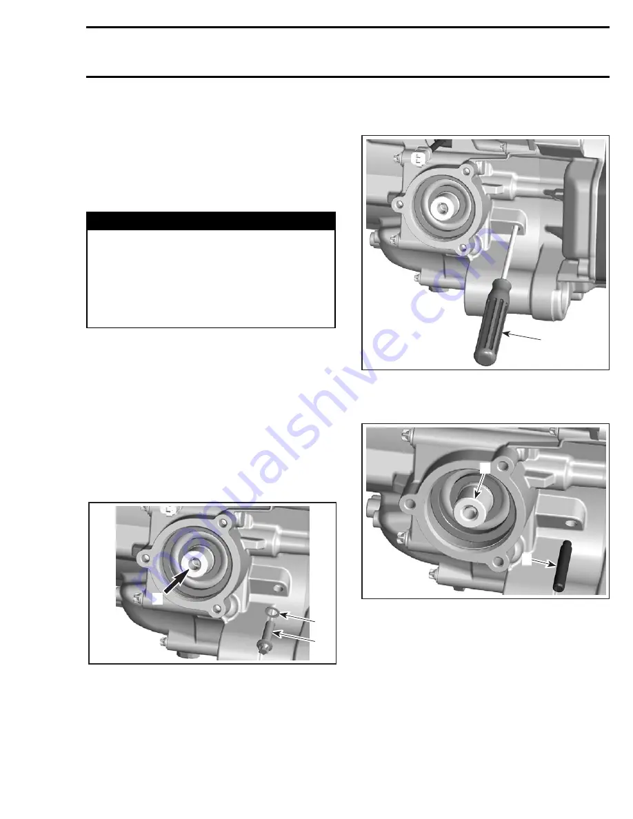
Remove screw
no. 1
and sealing washer
no. 2
.
1. Screw
2. Sealing washer
3. Output shaft on front side of vehicle
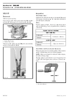
Use a screwdriver to check if groove in crankshaft
is aligned with the hole.
1. Screwdriver
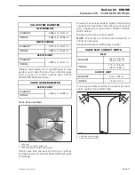
Lock crankshaft with crankshaft locking bolt (P/N
529 035 617).
1. Crankshaft locking bolt
2. Front output shaft area
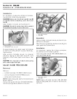
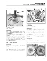
Install camshaft locking tool (P/N 529 035 926).
NOTE:
At piston TDC, the printed marks on the
camshaft timing gear have to be parallel to cylinder
head base as per following illustration.
WARNING
Torque wrench tightening specifications must
strictly be adhered to.
Locking devices (ex.: locking tabs, elastic
stop nuts, self-locking fasteners, etc.) must
be installed or replaced with new ones where
specified. If the efficiency of a locking device
is impaired, it must be renewed.
R400motr234A
1
2
3
1
R400motr235A
R400motr236A
1
2

