background image


15 


PARAMETER CHECKING AND ADUSTMENT


Parameter list


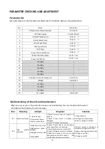
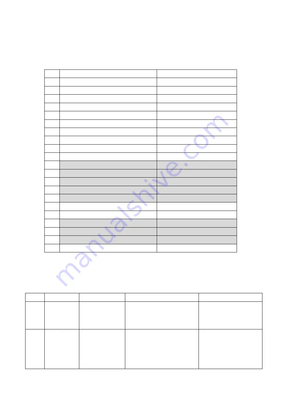
Some parameters can be checked and adjusted by the controller. Below is the parameter list. 


No. 

Name 

Instruction 

Compressor running Frequency 

Current hz 

EEV Open degree 

Current Value/5 

Ambient Temperature 

Current 


Outlet Water Temp. 

Current 


Exhaust gas Temp. 

Current 


Return gas Temp. 

Current 


Coil Temp. 

Current 


4-way Valve outlet Temp. 

Current 


Water Circulaton Pump 

0-off

1-on 

10 

4-way Valve Status 

0-off

1-on 

11 

Standby 

12 

Standby 

13 

Standby 

14 

Standby 

15 

Standby 

16 

Running Current of Compressor 

Current*10 

17 

Voltage 

Current/10 

18 

Standby 

19 

Standby 

20 

Standby 

21 

Fan speed 

Current/10 


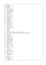
Malfunctioning of the unit and maintenance 

When an error occurs or the protection mode is set automatically, the circuit board and the wired 
controller will both display the error message. 

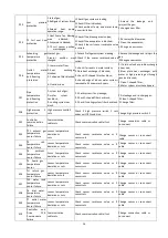
Error 

Meaning 

Analysis 

Diagnosis 

Solution 

P01 

Water Flow failure 

1.


No water flow; 

2.


Flow switch failure; 

3.


Water system block. 

1.Check  if  water  in  valve  is  closed  or  no 
water in; 
2.Check  if  flow  switch  is  blocked  or 
damaged; 
3.Check if“Y”Shape filter blocked. 

1.


Open the valve; 

2.


Change a new flow switch; 

3.Clean or change a new filter. 

P02 

High 

pressure 

protection 

1.Water flow is too small 
2.High-pressure  switch  is 
damaged; 
3.Refrigerant  system  block


4.EEV deadlock. 

1.Check  if  water  flow  is  not  enough  or 
water pump flow is not enough; 

2.Check if high-pressure switch is off; 

3.Check if refrigerant system is blocked; 

4.When  heat  pump  is  off  and  turn  the 
heat pump on and off to check if        EEV 
can be listenned by sound of reset. 

1.Reinject    water  or  change  to  a 
new pump of larger water flow; 
Change a new high-pressure switch; 
3.Change a new filter; 
4.Change a new EEV 

Summary of Contents for Eco Full Inverter EFI 14

Page 1: ...0 EFI Series Heat Pumps Installation and Operation Manual Eco Full Inverter Swimming Pool Heat Pump ...

Page 2: ...0 ...

Page 3: ...mps which has been designed to be as Eco friendly as possible using market leading technology and experience The EFI is a smart heat pump which controls how to heat your pool most efficiently and maintain pool temperature thanks to the full inverter technology Our goal is to provide you with an exceptional high performance qualityproduct We have produced this manual to assist you in getting the ge...

Page 4: ...1 ...

Page 5: ...TMENT 15 Parameter list 15 Malfunctioning of the unit and maintenance 15 MAINTENANCE THE UNIT 18 Cleaning the pipe system in the heat exchanger 18 Cleaning the air system 18 Winter Shutdown Lay up 18 TROUBLESHOOTING 19 ENVIRONMENTAL INFORMATION 19 DISPOSAL REQUIREMENTS 20 WIRING DIAGRAM 21 Specification 22 ENVIRONMENTAL INFORMATION 23 DISPOSAL REQUIREMENTS 23 User Manual for APP 27 READ THIS MANUA...

Page 6: ...a long life span of heat pump free from corrosion and rust By using of titanium heat exchanger the heat pump could be applied with all types of water treatment such as chlorine mineral bromine and salt water pools and spas Multiple functions Cooling and heating Auto functions available Auto operation Auto restart Auto defrost Timer on off no human attendance is required Wide ambient working condit...

Page 7: ...on to prevent the asphyxia caused by the leakage of refrigerant Use the specified electrical wires and attach the wires firmly to the terminal board connection in such a way that the stress of the wires is not applied to the sections Unit must be installed according to AS NZS 3000 2018 wiring rules and the electrical connection must be complete by a licensed electrician Incorrect connection and fi...

Page 8: ...ld goods could get wet and bedamaged Do not clean the unit when the power is ON Always shut OFF the power when cleaning or servicing the unit If not it could cause an injury due to the high speed running fan or an electricalshock Do not continue to run the unit when there is something wrong or there is a strange smell The power supply needs to be shut OFF to stop the unit otherwise this may cause ...

Page 9: ...please make sure that all parts are found inside the box The Unit Box Item Image Quantity Eco Full Inverter Swimming pool heat pump 1 Installation and Operation Manual 1 Barrel Unions 40mm 2 Winter Cover 1 Rubber foots for anti vibration 4 Water Drainage Pipe 1 ...

Page 10: ...6 OVERVIEW OF THE UNIT Unit Dimension MODEL EFI 14 EFI 17 EFI 23 A 986 986 1076 B 668 668 720 C 366 366 442 D 405 405 456 E 608 608 628 F 106 106 116 G 380 380 330 H 189 189 219 I 123 123 158 ...

Page 11: ...rol components 17 High pressure valve 5 Fin heat exchanger 18 Low pressure switch 6 Left panel 19 Power waterproof cover 7 Motor bracket 20 Needle valve 8 DC fan motor 21 Controller 9 Middle panel 22 Four way valve 10 Fan 23 Right panel 11 Front Panel 24 Titanium tube heat exchanger 12 Discharge grill 25 Electronic expansion valve 13 Reactance waterproof box ...

Page 12: ...ure controller Make sure that the discharged air will not be breathed in To perfect your installation Avoid directing the flow of ventilated air towards a sensitive noise zone such as room window Avoid positioning pool heat pump on a surface that can transmit vibrations to dwelling Try to avoid placing appliance under a tree or exposed to water or mud which would be likelyto complicate maintenance...

Page 13: ...he condensate drain kit 1 Install your heat pump by raising it by at least 10 cm using solid moisture resistantstuds 2 Connect the exhaust hose to the drain hole located underneath the heat pump Hydraulic Connection The filter must be cleaned regularly to ensure that the water in the system is clean and to avoid any problems related to dirt or clogging of the filter ...

Page 14: ...EFI 14 3x2 5mm 2 AWG 14 EFI 17 3x2 5mm 2 AWG 14 EFI 23 3x4 0mm 2 AWG 12 The above wiring information is to be used as a guide only Electrical connection must be made in accordance with AS NZS 3000 2018 wiring rules Use the cable glands and grommets provided inside the heat pump to routecables Trial running If the length of your cable is more than 10 meters we advise you to seek advice from a profe...

Page 15: ...nts described previously are strictly adhered to ATTENTION THE HEAT PUMP ONLY FUNCTIONS WHEN WATER FLOW IS PRESENT Then you can start up the heat pump following every point in the beloworder Open by pass valves Start pool system pump Turn on pool heat pump Set regulation OPERATING THE UNIT Operating the unit comes down to operating the digitalcontroller ALWAYS ENSURE CONTROLLER IS DRY TO TOUCH NEV...

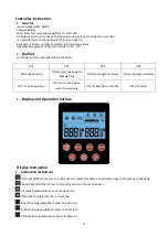
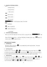
Page 16: ...beep sound ON for sound whenwater flow warning ON for back lighton always ON for self diagonisestatus OFF for no beep sound OFF for no soundwhen water flowwarning OFF for back light onfor 30s OFF for normal 3 Display and Operation Surface Display Instruction 1 Instruction for Buttons Start on off Short press to turn Also user can press this button to exit when they finish setting or checking Runni...

Page 17: ...unction 1 Switch Modes When heat pump is on short press to switch Heat Cool Auto each mode is available for selecting Boost Smart Silent threemodes 2 Set Temperature When heat pump is on short press or into water temperature setting surface Water in area temperature value twinkles press or to select value press to confirm and exit current setting No any set up after 30 seconds the controller will ...

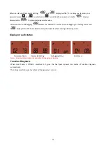
Page 18: ...r pump debugging 02 testing mode and displays ON or Off The related mode symbol twinkles after entering into testing mode Display on each status ParameterQuery ParameterSetting Debugging Status Error Query Note Value twinkles means it is available for changing or in verse Function Diagnosis When Heat Pump is off Dial 4 switches to 1 give the heat pump power into status of function diagnosis automa...

Page 19: ...tomatically the circuit board and thewired controller will both display the errormessage Error Meaning Analysis Diagnosis Solution P01 Water Flow failure 1 No water flow 2 Flow switch failure 3 Water system block 1 Check if water in valve is closed or no water in 2 Check if flow switch is blocked or damaged 3 Check if Y Shape filter blocked 1 Open the valve 2 Change a new flowswitch 3 Clean or cha...

Page 20: ...Fix leakage and re charge gas 2 Clean Y shaped filter 2 Change filter P08 High pressue 2 protection High pressure switch 2 cuts Check if high pressure switch 2 cuts under unit OFF condition Change high pressure switch 2 E01 Controller communication failure Communication cable cuts Check communication cable if cut Change connection cable or re connect E02 TP1 exhaust gas temperature sensor failure ...

Page 21: ...ailure E21 Compressor lack phase E22 IPM module reset E23 Compressor over current E24 PFC module extra high temperature E25 Current detection Circuit failure E26 out of step E27 PFC module temperature sensor abnormity E28 communication failure E29 IPM module extra high temperature E30 IPM module temperature sensor failure E31 reserved E32 IPM adjustment data E33 IPM adjustment data E34 AC input vo...

Page 22: ...ilator and condensate outflow should be cleaned of contaminants leaves twigs etc before each new heating period These types of contaminants can be manually removed using compressed air or by flushing with cleanwater It may be necessary to remove the device cover and air inlet gridfirst Attention Before opening the device ensure that all circuits are isolated from the powersupply To prevent the eva...

Page 23: ...ture level cannot be reached Please check whether The permissible operating conditions for the heat pump have been adhered to airtemperatures too high or too low The air inlet or outlet area is blocked restricted or very dirty There are closed valves or stop cocks in the water pipes The scheduled timer does work but the programmed actions are executed at the wrong time e g 1 hour too late or too e...

Page 24: ...ry to dismantle the system yourself the dismantling of the system treatment of the refrigerant of oil and other parts must be done by a qualified installer in accordance with relevant local and national legislation Units must be treated at a specialized treatment facility for re use recycling and recovery By ensuring that this product is disposed of correctly you will help to prevent potential neg...

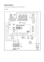
Page 25: ...21 WIRING DIAGRAM Please refer to the wiring diagram on the electricbox Model EFI14 17 23 ...

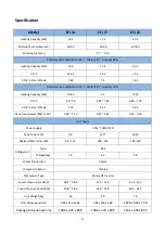
Page 26: ...C O P in Smart Mode 5 76 5 71 5 65 Max input power KW at 15 0 38 2 17 0 47 2 64 0 61 3 60 Unit Specs Power Supply 240v 50Hz 1PH Max Current A 9 6 13 77 18 36 Advised Water Flow LPM 85 115 100 135 200 250 Refrigerant Type R32 Charged kg 1 5 1 6 1 8 Water Connection 50mm Compressor Brand Toshiba Compressor Type Rotary DC Inverter Sound Pressure 1m dB A 38 5 48 6 41 5 52 5 44 2 54 5 Sound Pressure 10...

Page 27: ...of other parts must be donein accordance with relevant local and nationallegislation Your product is marked with this symbol This means that electrical and electronicproducts shall not be mixed with unsorted household waste Do not try to dismantle the system yourself the dismantling of the system treatment of the refrigerant of oil and other parts must be done by a qualified installer in accordanc...

Page 28: ...24 ...

Page 29: ...25 User Manual for APP Application EFI Full Inverter Series ...

Page 30: ...26 CONTENT Download the APP 27 Register 28 Configuration of APP 29 Operation of APP 33 PLEASE DO NOT THROW IT AWAY KEEP IT IN YOUR FILES FOR FUTURE REFERENCE ...

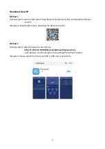
Page 31: ...stall it ISO system Scan the QR code to download the APP and install it Method 2 Android system Please browse the internet site http 47 254 152 109 8080 scadaiot downFile execute do with Browser of Android system to download the APP and install it ISO system Please search the Pool panel APP in APP store and install it ...

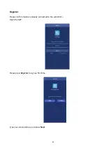
Page 32: ...28 Register Please confirm mobile is already connected to the valid Wi Fi Open the APP Please press Register to sign up first time Type your email address and press Next ...

Page 33: ...ord confirm and press Finish for sign up After sign up successfully the interface will change to Log in interface automatically Notes The password should be only combined with alphabet and numbers Configuration of APP Input Email address or Username password and press Sign in button ...

Page 34: ...30 Press button Connect heat pump and the interface will be change to next interface According to the introduction in the interface please operate After the heat pump unit setting please press Next ...

Page 35: ...31 Please in this interface select your router in your home LAN Input your router s password and please click Binding and Next ...

Page 36: ...or Android system the interface will directly skip to setting menu of mobile to select HF LPB130 For ISO system please manually enter the setting menu of mobile to select HF LPB130 Till now the connection is finished between mobile and heat pump unit successfully the interface will be change to main user interface ...

Page 37: ...tton 2 Operating mode and function icon 3 Setting temperature icon 4 Ambient temperature 5 Temperature setting bar 6 Mode setting button 7 Inquire button 8 Fault button 9 Function setting button 10 On Off button 11 Add heat pump unit button 12 Refresh button ...

Page 38: ...P c Reset the APP password d Sign out the APP 2 On Off button Press On Off button under the status of unit stand by the unit will be run During the unit runs press this button and the unit will be stopped 3 Mode setting button This button is used to select the operating mode which includes Auto Cooling and Heating Once press it the interface will be enter mode selection interface In this interface...

Page 39: ... Heating mode Auto mode 4 Function setting button This button is used to select the operating function which includes boost smart and silence mode Once press it the interface will be enter mode selection interface In this interface you can set boost mode smart mode or silence mode After selection please press Confirm to confirm ...

Page 40: ...e mode Smart mode Boost mode 5 Inquire button Press Inquire button the inquire interface will be displayed From this interface the following current parameter of the heat pump unit will be displayed a Ambient temperature b Outlet water temperature c Inlet water temperature d Unit malfunction state e Compressor output rate ...

Page 41: ...37 6 Fault button Press Fault button and the fault records include history and current error or protection codes will be displayed ...

Page 42: ...ng steps 8 Refresh button Press this button the displayed current setting temperature and ambient temperature in screen will be refreshed 9 Temperature setting bar By finger slide the slider along the temperature bar to set the required temperature At the same time the displayed temperature value above the temperature bar will be changed following different locations of the slider ...

Page 43: ...r ISO system you want to change ISO or Android system mobile phone and please following steps a Press the adjustment buttons of heat pump controller at the same time till you hear the prompt sound b Please set the APP and the heat pump again follow previous steps ...

Page 44: ...40 Australian Energy Systems Unit 17 6 Maunder St Slacks Creek Queensland 4127 Phone 07 3299 2700 Web www poolheating com au Email reception poolheating com au ...

Reviews: