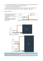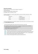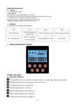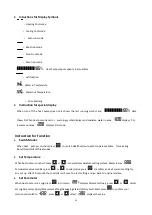
19
TROUBLESHOOTING
This section provides useful information for diagnosing and correcting certain troubles which may occur.
Before starting the troubleshooting procedure, carry out a thorough visual inspection of the unit and look
for obvious defects such as loose connections or defective wiring.
Before contacting your local dealer, read this chapter carefully, it will save you time and money.
WHEN CARRYING OUT AN INSPECTION ON THE SWITCH BOX OF THE UNIT, ALWAYS MAKE SURE THAT
THE MAIN SWITCH OF THE UNIT IS SWITCHED ‘OFF’.
The guidelines below might help to solve your problem. If you cannot solve the problem, consult your
installer/local dealer.
The heat pump will not run.
Please check whether:
There is supply voltage (tripped fuse, power failure).
The operating switch on the wired controller is switched on, and whether the correct set point
temperature has been set.
The set temperature level cannot be reached. Please
check whether:
The permissible operating conditions for the heat pump have been adhered to (air temperatures
too high or too low).
The air inlet or outlet area is blocked, restricted or very dirty.
There are closed valves or stop-cocks in the water pipes.
The scheduled timer does work but the programmed actions are executed at the wrong time (e.g. 1 hour
too late or too early).
Please check whether:
The clock and the day of the week are set correctly, adjust if necessary.
If you cannot correct the fault yourself, please contact your after-sales service technician. Work
on the heat pump may only be carried out by authorized and qualified after-sales service
technicians.
ENVIRONMENTAL INFORMATION
This equipment contains fluorinated greenhouse gases covered by the Kyoto Protocol. It should only be
serviced or dismantled by professional trained personnel.
This equipment contains R32 refrigerant in the amount as stated in the specification. Do not vent R32 into
the atmosphere: R32, is a fluorinated greenhouse gas with a Global Warming Potential (GWP) = 675.
Summary of Contents for Eco Full Inverter EFI 14
Page 2: ...0 ...
Page 4: ...1 ...
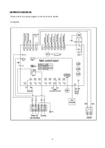
Page 25: ...21 WIRING DIAGRAM Please refer to the wiring diagram on the electricbox Model EFI14 17 23 ...
Page 28: ...24 ...
Page 29: ...25 User Manual for APP Application EFI Full Inverter Series ...


