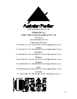
Rear Panel
6. Balanced Input
A female 3-pin XL type connector is provided on
each input:
Pin 1 = Signal Ground;
Pin 2 = Hot (non-inverting or in phase);
Pin 3 = Cold (inverting or reverse phase).
6a.Signal Strapping
A male 3-pin XL type connector is provided and
wired in parallel with the female input XLR for
strapping / looping signal between amplifiers.
7. SPEAKON Output Connector
The NEUTRIK (NL4MP) 4 way SPEAKON connector
is provided as the main speaker output termination.
This emerging standard of loudspeaker to amplifier
connection allows access to both channels of the
amplifier via the one connector for bi-amp
applications. Channel-A is considered the dominant
channel and has both channels wired to the Speakon
connector. See the installation section of this
manual for detailed information on Speakon wiring.
7a.Binding Post Outputs
Binding posts (banana jacks) are provided for
speaker output termination with banana plugs or
bare wire. The red post is used as positive and the
black post is used as negative.
8. Mains Lead
Your amplifier is supplied with a heavy duty mains
lead (power cord) appropriately rated for the mains
supply voltage marked on the rear panel of your
amplifier.
The wires in the mains lead are coloured in
accordance with the following code:
BROWN
= ACTIVE;
BLUE
= NEUTRAL;
GREEN AND YELLOW
= EARTH.
Controls & Connectors 9
! CAUTION !
Your amplifier must always be earthed!
9. Mains Circuit Breaker
A “push to reset” thermal acting circuit breaker is
supplied on your amplifier providing overall protection
of your amplifier’s power supply and the
interconnecting mains. The breaker will isolate the
"active" mains conductor in the event of a high
current internal fault or in continued overload
conditions.
The breaker will not be able to be reset immediately
after tripping. A cool down period of around 30
seconds is required before the breaker will reset
back into circuit. If the breaker "trips" immediately
after a reset, then a fault may have developed within
the amplifier.
10. D.C. Rail Fuses
Your
AM1600
amplifier is fitted with 10 Amp fuses
per rail - per channel, as overload protection for the
output stage of your amplifier.
These fuses are in series with the high current
supply rails to the amplifier's output stage and will
blow when:
1) An internal fault exists;
2) There is a sustained overload;
3) There is a sustained short circuit;
4) Sustained load fault.
Front Panel Indication will result if one of the
corresponding Rail Fuses is to "blow".
- The VU meter will light up fully and the positive
Output Rail LED will extinguish if the positive
supply Rail Fuse "blows".
- The Fault Indicator will light up and pulse in sync.
with the program source if the negative supply Rail
Fuse "blows".
Replace only with 10 Amp, 3AG fast acting type
fuses.


