background image


Australian Monitor 

1 Clyde Street, Silverwater NSW 2128 Australia 

+61 2 9647 1411 

www.australianmonitor.com.au


SERVICE INFORMATION 


AMC+120 

MIXER AMPLIFIER 


CONTENTS:  

OPERATION MANUAL 

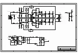
SCHEMATIC DIAGRAMS 

COMPONENT OVERLAYS 

TEST PROCEDURE 

REPLACEMENT PARTS LIST 

SERVICE BULLETIN 


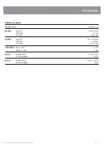
Summary of Contents for AMC120

Page 1: ...ilverwater NSW 2128 Australia 61 2 9647 1411 www australianmonitor com au SERVICE INFORMATION AMC 120 MIXER AMPLIFIER CONTENTS OPERATION MANUAL SCHEMATIC DIAGRAMS COMPONENT OVERLAYS TEST PROCEDURE REPLACEMENT PARTS LIST SERVICE BULLETIN ...

Page 2: ...AMC SERIES 30W 60W 120W 250W MIXER AMPLIFIERS INSTALLATION AND OPERATION MANUAL ...

Page 3: ...fan intake or exhaust ports Do not operate equipment on a surface or in an environment which may impede the normal flow of air around the unit such as a bed rug weathersheet carpet or completely enclosed rack If the unit is used in an extremely dusty or smoky environment the unit should be periodically blown free of foreign matter 14 Do not remove the cover Removing the cover will expose you to po...

Page 4: ...Rev B 6th Jun 2006 Rev C 26th May 2008 This symbol is intended to alert the user to the presence of uninsulated dangerous voltage within the products enclosure that may be of sufficient magnitude to constitute a risk of electric shock to persons This symbol is intended to alert the user to the presence of important operational and maintenance servicing instructions in the literature accompanying t...

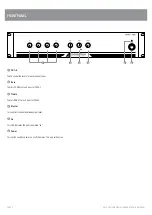
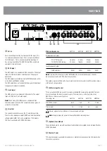
Page 5: ...each channel input 2 Bass There is 12dB of cut and boost at 100Hz 3 Treble There is 9dB of cut and boost at 10kHz 4 Master This controls the overall mixed output level 5 On This LED indicates the unit is powered on 6 Power This switch switches power on or off the mains The up position is on 5 6 2 3 4 1 ...

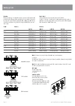
Page 6: ... available on 115V models 100V out is available on 230V 240V models Note Only connect one output either Distributed Line or Low Impedance per channel Do not connect LowZ and 70 100V at the same time The output strip comes fitted with a touch proof cover held in place by two M3 machine screws with flat and spring washers 5 IEC Mains Input Socket This is a standard IEC 3 pin socket It accepts a stan...

Page 7: ... 0 75mm2 AWG16 1 5mm2 AWG13 2 5mm2 70V Up to 50m AWG26 0 12mm2 AWG24 0 2mm2 AWG22 0 35mm2 AWG18 0 75mm2 50m 200m AWG20 0 5mm2 AWG18 0 75mm2 AWG16 1 5mm2 AWG13 2 5mm2 Over 200m AWG18 0 75mm2 AWG16 1 5mm2 AWG13 2 5mm2 AWG10 6 0mm2 4 ohm Up to 10m AWG18 0 75mm2 AWG18 0 75mm2 AWG18 0 75mm2 AWG18 0 75mm2 10m 30m AWG13 2 5mm2 AWG13 2 5mm2 AWG13 2 5mm2 AWG13 0 35mm2 Over 30m Not Recommended Not Recommend...

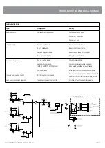
Page 8: ... at source Reduce volume levels on front panel Reduce Bass control level No sound but amp is on Volume controls down Amplifier has overheated AMC 60 AMC 120 AMC 250 only DC fuse s blown Check volume controls Check for obstructions above and below Make sure the amplifier is well ventilated Refer product to local Australian Monitor dealer No sound from channels 2 and 3 Priority function is being use...

Page 9: ...nts PRIORITY Channel 1 will mute channels 2 3 and 4 This will only occur when signal appears on channel 1 irrespective of the channel volume control Priority can be disabled See below The release time is approx 3 secs and is NOT adjustable The mute depth is approx 40dB and is not adjustable ...

Page 10: ...PAGE 9 AMC SERIES INSTALLATION AND OPERATION MANUAL dimensions ...

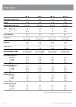
Page 11: ...16 5lb 23 1lb 27 6lb 30 8lb SHIPPING DIMENSIONS WXHXD 510 x 145 x 297mm 525 x 175 x 385mm 525 x 175 x 385mm 525 x 185 x 470mm 20 1 x 5 7 x 11 7 20 7 x 6 9 x 15 2 20 7 x 6 9 x 15 2 20 7 x 7 3 x 18 5 MAINS CURRENT DRAW 240V FULL POWER 0 35A 0 66A 1 20A 2 53A 1 3 POWER 0 23A 0 44A 0 80A 1 61A 1 8 POWER 0 17A 0 32A 0 55A 1 10 IDLE 0 08A 0 13A 0 15A 0 15A MAINS CURRENT DRAW 115V FULL POWER 0 73A 1 38A ...

Page 12: ...n 0 5 MIC INPUT SENSITIVITY 1mV 200ohm IMPEDANCE 1k3 ohm HEADROOM 77mV 37dB AUX INPUT SENSITIVITY 0 5V 100kohm IMPEDANCE 200kohm HEADROOM 15V 30dB TONE CONTROL BASS 100HZ 12 dB TREBLE 10KHZ 9 dB LINE OUT NOMINAL OUTPUT 0 775V 1kohm OUTPUT IMPEDANCE 100ohm REC OUT NOMINAL OUTPUT 250mV 10kohm OUTPUT IMPEDANCE 1kohm ...

Page 13: ... 31 Walsh Street Thebarton SA 5031 PO Box 157 Hindmarsh SA 5007 Phone 08 8352 4444 Fax 08 8352 4488 Email sa audiotelex com au PERTH WA SALES 3 11 Howe Street Osborne Park WA 6017 PO Box 1281 Osborne Park BC WA 6916 Phone 08 9204 0200 Fax 08 9244 3783 Email wa audiotelex com au AUCKLAND NZ SALES 9C Piermark Drive Albany 0752 New Zealand PO Box 300 512 Albany 0752 Phone 09 415 9426 Fax 09 415 9864 ...

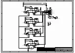
Page 14: ...C6 470p R20 1K R21 1K C22 4u7 C21 4u7 C25 4u7 C17 10 25 NP C18 10 25 NP C16 10 25 NP 1 2 3 4 7 6 5 7 6 5 8 8 VCC AG 1 2 VCC TAPE OUT GRD CH 1 OUT CH 2 OUT CH 3 OUT TAPE OUT LINE OUT MIX OUT MIX OUT 1 2 3 4 5 6 7 8 9 10 CN1 CON10 VCC VCC VCC G L R RCA1A RCA 4POLE G L R RCA1B RCA 4POLE G L R RCA2A RCA 4POLE 3 2 1 XLR1 XLR FEMALE 3 2 1 XLR2 XLR FEMALE 3 2 1 XLR3 XLR FEMALE 3 2 1 XLR5 XLR MALE C24 10 ...

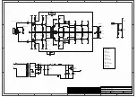
Page 15: ... 22k R3 1k5 R1 220n C1 4 7u 25 C3 T3 BD139 T1 C1815 10k R44 24V BIAS BIAS 24V Driven by balanced signal 1k R21 1k R22 BIAS 0R R23 0R R26 D2 1N4007 D1 1N4007 T5 BC639 T6 BC639 R28 56R R27 R29 56R R30 C5 C6 2200u 63V F1 8 A 150R 5W X 2 R39 230V PRIM1 39 5V F2 HRC 120W 2A 60W 1 6A D3 6A04 D4 D5 6A04 D6 VC Mains 230 240 V 0 39R 5W R36 T12 TIP35C Vc 0 39R 5W R35 T11 TIP35C Vc PRIM2 39 5V T16 BD139 R40 ...

Page 16: ... Vc Vc Vc 470R R18 100R R17 10k R13 47k R14 1k R11 2k2 R8 100R R7 330k R4 22k R3 1k5 R1 220n C1 4 7u 25 C3 T3 BD139 T1 C1815 10k R44 24V BIAS BIAS 24V Driven by balanced signal 1k R21 1k R22 BIAS 0R R23 0R R26 D2 1N4007 D1 1N4007 T5 BC639 T6 BC639 56R R28 56R R27 56R R29 56R R30 C5 2200u 63V C6 2200u 63V F1 150R 5W X 2 R39 115V PRIM1 39 5V F2 D3 6A04 D4 6A04 D5 6A04 D6 6A04 VC Mains 230 115V 0 39R...

Page 17: ... VCC Signal Signal 220E R27 TO AMP TO AMP C4 4 7u C14 4 7U R23 10K R24 10K C19 47 25V VCC VCC 1 2 3 4 5 6 7 8 9 10 CN1 TH TH IN IN TH TH VCC IN IN 1 2VCC R33 4k7 R29 10K R30 2K2 GND 12V R31 220E 2W C21 1000 25 1 2 3 4 5 6 CN2 R32 1K5 CN3 LED1 1 2 3 PRIORITY VCC VCC VCC C17 10 25 T2 C1815 2 3 1 4 IC3A LM833 6 5 7 8 IC3B LM833 2 3 1 4 IC4A LM358 6 5 7 8 IC4B LM358 6 5 7 8 IC1B LM833 2 3 1 4 IC1A LM8...

Page 18: ...R25 R27 R21 R24 R23 C29 RCA3 J2 J1 XLR4 C25 R22 R21 XLR1 XLR2 XLR3 RCA2 C21 C22 C11 C20 C19 C24 C23 C9 C17 C16 C13 C10 C8 C18 C15 C14 C12 C7 C5 C6 C3 C1 C2 R19 R20 R16 R13 R17 R9 R12 R10 R7 R11 R8 R14 R6 R5 R15 R4 R3 R2 R1 IC2 IC1 R18 C4 S1 R28 R29 R30 R31 R32 R33 R34 R35 J4 J5 J6 C32 AMC input E A59 ...

Page 19: ...R3 VR2 T4 T3 T1 R47 R46 R40 R39 R38 R37 R36 R34 R33 R32 R31 R30 R29 R28 R27 R26 R25 R24 R23 R21 R19 R18 R17 R16 R15 R13 R12 R11 R10 R8 R7 R6 R5 R4 R3 R2 R1 PRIORITY IC4 IC1 D6 CN3 D4 D3 D2 D1 CN2 CN1 C20 C19 C17 C16 C15 C14 C13 C12 C11 C10 C9 C8 C7 C4 C3 C1 R20 R22 C21 IC3 T2 C2 T6 R14 R9 J16 J15 J13 J12 J10 J10 J9 J8 J7 J7 J6 J5 J4 J3 J3 J2 J1 J14 J17 ...

Page 20: ...J4 J6 R26 T8 PR1 T1 R29 R30 J10 R37 R33 R35 R38 T13 T9 T11 T10 T14 T12 R15 R17 R20 R13 R11 R8 R4 R3 R44 R10 R45 C4 C3 R12 F1 T3 T4 T1 T2 T5 T6 T15 D1 D2 R27 R24 J5 J11 R21 R31 R23 J1 R32 R22 J12 J13 J8 J9 J7 R42 R43 R1 C2 C1 T7 D6 R6 C15 R19 R18 R28 R14 R5 R9 R16 R7 CN1 R R34 C8 C7 C17 C16 CN2 CN3 C9 C10 R41 ...

Page 21: ...wer up 3 1 Voltages 3 2 Bias setup 4 Initial AC Checks 4 1 Signal check and gain of amp 4 2 Emitter current check 4 4 Outputs 4 5 Phantom power 5 THD 6 Sensitivity 6 1 Input 7 Bandwidth 8 Phase 9 Current Limit 10 Noise floor SNR 11 Fan Thermal check 12 Final check for damage 13 Factory setting 14 Listening Test 14 1 Switch on thump 14 2 Audio quality 14 3 Current Limit ...

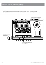
Page 22: ...est 2 1 Fuse check 2 x AC fuses 2A 20x5mm 1 x DC fuses 8A 20x5mm 2 2 Connections Connect amplifier to Variac 0Vac Signal generator mic1 no signal Resistive load 4ohm on 4ohm terminal with meters oscilloscope 2 3 Reset controls Volume control to minimum PR1 preset on the amplifier PCB CCW 3 Power up Turn on power switch and adjust voltage to 230VAC Watch current meter for excess current draw P F Cu...

Page 23: ... shall be 21 9VAC 2VAC 4 2 Emitter current check Setup Signal generator 260mVAC 1kHz Signal in XLR Master pot max CCW Output metering 4ohm out Load 4ohm Procedure Set output to 15VAC using master volume control Check voltage across emitter resistors of power devices P F Voltage shall be between 150mVDC 250mVDC 4 3 Outputs Setup Signal generator 260mVAC adjusted for 21 9V out with pots max 1kHz Sig...

Page 24: ...tivity 6 1 Inputs Setup Signal generator 260mVAC 1kHz Signal in XLR Master pot max CW Output metering 100Vout Load 80ohm Procedure Set channel pot to max P F The output reading shall be 100VAC 10VAC 7 Bandwidth Setup Signal generator 260mVAC 1kHz Signal in XLR Master pot max CW Output metering 100Vout Load 80ohm Procedure Set the volume pot so the output is 70VAC Adjust the frequency on the signal...

Page 25: ...1kHz Signal in XLR Master pot min CCW Output metering 100Vout Load 80ohm Procedure Change the load to 40ohms Increase the signal such that at 65VAC you can see the overload protection coming on with a rounding of the sine wave If it is there then reduce the voltage to 30VAC out Short the unit for 10sec Release the shorting link and check for the output P F The output shall be reading 30VAC 1V 10 N...

Page 26: ...heating of the heatsink P F The output shall mute to 10V at a temp between 90 115degC Values to be recorded Value Pass Range 11b Thermal cutout 90degC 115degC 12 Final check for damage Disconnect from test bench and inspect for scratches on external paint 13 Factory setting Set up the unit for default factory setting as below Pot positions a Master volume min Attach tested sticker ...

Page 27: ...the setup Keep all pots full tone at center 14 1 Switch on thump Switch on the set and check for any ON Thump Ensure unit does not thump Check that no low frequencies are audible Make all pots minimum 14 2 Audio quality Check CD Player output 14 3 Current Limit Short the output with signal ON Signal should mute and return ...

Page 28: ...50OPB BR025001 Transformers AMC 30 mains transformer AMC 30TX BR030123 AMC 30 output transformer AMC 30OT BR030124 AMC 60 mains transformer AMC 60TX BD6041 AMC 60 output transformer AMC 60OT BD060127 AMC 120 mains transformer AMC 120PTX BD0642 AMC 120 drive transformer BR0120036 BR0120036 AMC 120 output transformer AMC 120OT BR0120125 AMC 250 mains transformer AMC 250TX BR0250140 AMC 250 output tr...

Page 29: ...ing the existing mains fuse with name brand quality fuses available from Element14 as follows 115V Operation North America 230V Operation Australia Europe Model Fuse Rating Element14 Fuse Rating Element 14 AMC 30 T1A 1123115 T500mA 1123121 AMC 60 T3 15A 1123119 T1 6A 1123113 AMC 120 AMC 120P T4A 1123120 T2A 1123118 AMC 250 AMC 250P AMC 1202P T8A 1123125 T4A 1123120 All fuses are Cooper Bussman 250...

Reviews: