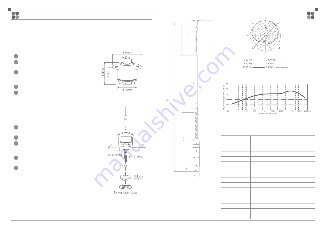
450mm [18in]
Ø8mm
[0.31in]
Ø19mm
[0.75in]
Ø20mm
[0.79in]
Ø8mm
[0.31in]
98.5mm [3.88in]
81mm
[3.19in]
74mm
[2.91in]
98mm
[3.86in]
Ø6mm
[0.24in]
13.03mm
[0.51in]
Ø7.3mm
[0.29in]
( ªø«× 162±3mm)
The shock mount is designed to be flush mounted and provides isolation to reduce room
rumble and mechanical noises from being amplified.
Installing AMSLIMG into the Shock Mount
1
To install the AMSLIMG into the Shock Mount unscrew
the bottom plastic screw collar.
2
Slide the AMSLIMG body into the Shock Mount.
3
Re-install the bottom plastic screw collar until snug.
Be careful not to cross thread or crack the plastic screw
collar.
4
Insert a female 3-pin XLR connector into the microphone
base.
5
Phantom power is required for the AMSLIMG to operate.
To avoid possible loudspeaker damage ensure the PA
system is muted first before you enable phantom power.
Once phantom power is enabled the LED located on the
body of the AMSLIMG will illuminate.
Installing the shock Mount
1
Choose a suitable flat surface to install the shock mount.
2
Using a hole saw cut a 51mm (2inch) diameter hole
through the mounting surface
3
Slide the shock mount into the freshly cut hole and mark
the location of the three screw holes using a marker or
punch.
4
Using a 3.0mm drill pre-drill three pilot holes.
5
Insert the shock mount into the hole again and fasten
down the shock mount with the 3 screws provided.
PAGE 2
PAGE 3
AMSLIMG GOOSENECK MICROPHONE
INSTRUCTION MANUAL
INSTALLING SHOCK MOUNT & AMSLIMG MICROPHONE
DIMENSIONS
TYPICAL POLAR PATTERNS
TYPICAL FREQUENCY RESPONSE
Specifications
Transducer Type
Electret condenser Ø 6mm
Polar Pattern
Cardioid
Frequency Response
50Hz – 16Khz
Sensitivity
11.2 mV/Pa -39 dBV
Electrical Impedance
200 Ω
Min. Load Impedance
1000Ω
Equivalent Noise Output 26 dB
Max. SPL
130dB @ 1% THD
Phantom Power V
9 – 52 V DC
Current Draw
3.0 mA
Finish
Matte Black
Connection
Balanced 3 pin XLR Male Pin 2 +, Pin 3 –, Pin 1 shield
Operating Temp
-10°C – 50°C 95% humidity max.
Dimensions
450 mm Length
Net Weight
160g
Included Accessories
Isolation shock mount, windsock
sales@wes.net.au
www.wes.net.au


