6. INSTALLATION
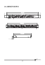
In its basic form, installation of the ZM3 is simply a matter of mounting the unit in a rack,
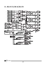
connecting sources to the appropriate inputs and connecting zone outputs to power
amplifiers.
The power supply should be securely mounted, and connected to the ZM3.
NOTE: XLR CONFIGURATION
When wiring the outputs on the ZM3 as unbalanced,
Pin2 should be wired as hot and Pin1 and Pin3
should be connected together and wired as
ground/shield.
REMOTE CONTROLS
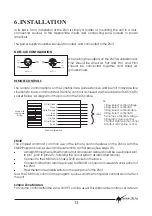
The remote control options on the ZoneMix3 are quite extensive and permit many possible
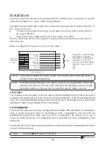
situations to be accommodated. Remote control is achieved via the rear panel RJ45 (CAT5)
socket. Below is a diagram of the pin out on the CAT5 cable.
The simplest and most common use of the remote control features on the ZM3 is with the
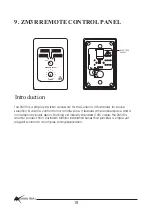
ZM3R Program Source select and level remote control panel (See page 18).
A straight through wired Cat5 cable (not a crossover cable) should be used (wired pin1
to pin1, pin2 to pin2 etc, following the colour system as indicated above)
Connect to the ZM3R which has a RJ45 socket on the back.
Connect cable from remote panel(s) to REMOTE connector in relevant zone section of
the ZM3.
Press the remote enable switch on the rear panel of the ZM3.
Now the ZM3R has control of the program sources and the front panel controls do not effect
the unit.
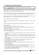
For volume control within the zone, an RC1 can be used. This will provide control over a stereo
ZM3R
Simple Zone Masters
!
!
!
!
White/Green 1
Green 2
White/Orange 3
Blue 4
White/Blue 5
Orange 6
White/Brown 7
Brown 8
568A configuration
CABLE
Shown with
locking clip
facing
1 Prog Select control Voltage
2 Prog Select control Bit 1
3 Prog Select control Enable
4 Prog Select control Bit 0
5 Volume control Ref Voltage
6 Program Volume control
7 Output Right Volume control
8 Output Left Volume control
PIN
INSTALLATION SERIES
Australian Monitor
13
PIN 2
HOT
+
PIN 3
COLD
-
PIN 1
GND
PIN 2
HOT
+
PIN 3
COLD
-
PIN 1
GND
FEMALE XLR
MALE XLR


