background image


© Austria Email AG 


id.: 17-14-35-1251-08 |  02.2016 


6.2 

Checks before starting 

Before starting the device, the following must be checked:

-


The hot water tank must be filled with water and ventilated.

-


All the seals must be tight. 

-


All protection elements must be functioning.

6.3 

Connection of the HP to the voltage power grid

The device is equipped with a power cord with a plug. Before starting, the power cable must be plugged into 
a socket with a voltage of 230 V a.c.
 
After plugging it in, the start-up sequence will be shown in the display. The settings are displayed one after 
the other. 
If the start sequence is not shown, contact customer service. 

6.4 

Operation 

If the heat pump is properly connected to the voltage and water sup
the  operating  programme  selected  or  >P1<  appears  on  the  screen,  as  well  as  all  parameters  and  their 
values. 30 seconds after the electric connection, the system starts and begins to heat the water.
The  heat  pump  switches  on.  After  reaching  the  pre
switches off automatically.  If the  water cools down  by 5°C, to  47°C, the  heat pump switches back on. The 
switch-off  temperature  can  be  selected  by  the  user  but  is  limited
regulator blockade). Water heating is limited to 60°C and cannot be adjusted. The ambient air temperature at 
which the system switches to  the replacement heat source has already  been set to 0°C. This temperature 
can be adjusted by the user as desired (following instructions).

6.5 

Settings 

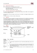
LED status lights 


Program key 


HT key


Flashing 
indicator 

Prog.  Description 

☼ does not 
light up 

  does not 

light up 

P0 

The heat pump is switched off and only the water temperature display is active in the 
tank. 

☼ lit 

  does not 

light up 

P1 

The heat pump heats the water only with the compressor to the set temperature. The 
warm water pump heats the water. At a temperature that too low, the compressor is 
switched off for safety reasons. 
Warning: In the case of a defective air sensor, this erro
still heated. 


Before starting the device, the following must be checked: 

The hot water tank must be filled with water and ventilated. 

All protection elements must be functioning. 

Connection of the HP to the voltage power grid 

The device is equipped with a power cord with a plug. Before starting, the power cable must be plugged into 
a socket with a voltage of 230 V a.c. 

up sequence will be shown in the display. The settings are displayed one after 

If the start sequence is not shown, contact customer service.  

If the heat pump is properly connected to the voltage and water supply, after 2 seconds the control version of 
the  operating  programme  selected  or  >P1<  appears  on  the  screen,  as  well  as  all  parameters  and  their 
values. 30 seconds after the electric connection, the system starts and begins to heat the water.

switches  on.  After  reaching  the  pre-set  switch-off  temperature  of  52°C,  the  heat  pump 

switches off automatically.  If the  water cools down  by 5°C, to  47°C, the  heat pump switches back on. The 

off  temperature  can  be  selected  by  the  user  but  is  limited  to  a  maximum  of  55°C  (temperature 

regulator blockade). Water heating is limited to 60°C and cannot be adjusted. The ambient air temperature at 
which the system switches to  the replacement heat source has already  been set to 0°C. This temperature 

justed by the user as desired (following instructions). 


The heat pump is switched off and only the water temperature display is active in the 

The heat pump heats the water only with the compressor to the set temperature. The 
warm water pump heats the water. At a temperature that too low, the compressor is 
switched off for safety reasons.  
Warning: In the case of a defective air sensor, this error is displayed but the water is 


5.2. 


24 

The device is equipped with a power cord with a plug. Before starting, the power cable must be plugged into 

up sequence will be shown in the display. The settings are displayed one after 

ply, after 2 seconds the control version of 

the  operating  programme  selected  or  >P1<  appears  on  the  screen,  as  well  as  all  parameters  and  their 
values. 30 seconds after the electric connection, the system starts and begins to heat the water. 

off  temperature  of  52°C,  the  heat  pump 

switches off automatically.  If the  water cools down  by 5°C, to  47°C, the  heat pump switches back on. The 

to  a  maximum  of  55°C  (temperature 

regulator blockade). Water heating is limited to 60°C and cannot be adjusted. The ambient air temperature at 
which the system switches to  the replacement heat source has already  been set to 0°C. This temperature 

Temperature 

Parameters  /  Alarm 
Display 


+/- keys


The heat pump is switched off and only the water temperature display is active in the 

The heat pump heats the water only with the compressor to the set temperature. The 
warm water pump heats the water. At a temperature that too low, the compressor is 

r is displayed but the water is 

Summary of Contents for WPA 233 ECO

Page 1: ...EN Operating and Installation Instructions Heat pump with air duct for heating hot water WPA 233 ECO WPA 303 ECO Please forward this on to the user ...

Page 2: ...on 08 as of 06 2016 Printed in Austria Copyright by Austria Email AG Protected by copyright Any use outside of the boundaries of the copyright without the consent of Austria Email AG is prohibited and punishable All previous versions are hereby rendered invalid The right to changes is reserved ...

Page 3: ...8 3 3 9 Recycling 8 3 3 10 Directives 8 4 Technical Description 9 4 1 General 9 4 2 Structure 10 4 3 Functional Description 11 4 4 Technical Data 13 5 Assembly 13 5 1 Product contents 13 5 2 Storage 13 5 3 Transport 13 5 4 Installation location of the HP 14 5 5 Installation 16 5 5 1 Hydraulic connections 16 5 5 2 Air duct connection 17 5 5 3 Condensate drain connector 18 5 5 4 Installation of the ...

Page 4: ...ourse our company is also glad to be at your disposal through the Customer Services and Sales Departments for any advice you may require Keep these instructions in a safe place and if applicable please pass them on to subsequent During the assembly maintenance and application of the heat pump there is the possibility of different er levels Certain sections of this guide contain R sets by means of ...

Page 5: ...f the equipment compliance with the installation instructions Servicing and the remedy of defects during the guarantee period are carried out by Austria Email AG When ordering spare parts for this device please provide the following information exact type designation of the product All the information needed to order spare parts can be found on a sign or sticker on the device The manufacturer s wa...

Page 6: ...s of the Member States relating to electrical equipment designed for use within certain voltage limits DIRECTIVE 2004 108 EC OF THE EUROPEAN PARLIAMENT AND OF THE COUNCIL from 15 December 2004 for the approximation of the laws of the Member States relating to electromagnetic tolerance and for the removal of the directive 89 336 EWG 2 3 2 Standards SIST EN 60335 1 2012 SIST EN 60335 2 40 2003 A1 20...

Page 7: ...ess in the event of a repair or maintenance If the water temperature in boiler exceeds 75 C while th heat pump is operating Customer Services must be informed immediately The device must be disconnected from the network before any work on the heat pump The heat pump must be set up in such a way that the mains plug is easily accessible at all times The device must be set up on a hard flat and non s...

Page 8: ...In the event of a fire use an appropriate extinguishing substance 3 Special hazards Pressure increase When exposed to air oxygen at certain temperatures and pressure conditions the formation of flammable substances can occur At high temperatures toxic and corrosive gases could be released 4 Special intervention methods use a fire extinguisher to cool the part of the device or the refrigerant that ...

Page 9: ...the respiratory organs In the event of insufficient ventilation the type AX protection mask Indoor use full face mask with the oxygen pipe Hand protection Protective gloves made of nitrite rubber or leather Eye protection safety glasses with side protection Skin protection Clothing made of cotton Industrial hygiene it is prohibited to drink eat or smoke at the workplace Waste products consult with...

Page 10: ...g hot water is to cool down a selected room e g cellar storage room etc Any change to or replacement of the original components and any improper or incorrect use of the device will nullify the manufacturer s liability guarantee and warranty Consequential costs of any damage which is caused must be paid by the user Dimensions WPA 233 ECO WPA 303 ECO A 85 mm 85 mm B 320 mm 320 mm C 700 mm 700 mm D 7...

Page 11: ... of supply water in 303 ECO is a unit comprising a water heater and assembly compressor evaporator fan etc The hood of the heat pump is made of plastic and has two pipe nozzles for connection to a pipe system The heat pump also offers the possibility of ventilating a selected room The assembly comprises compressor evaporator centrifugal ventilator dry filter copper and electric installation The he...

Page 12: ...n pressure is reduced and the cooling agent can continue to absorb heat from the suctioned air Water heater hot water tank The water heater is enamelled on the inside cased on the outside with polyurethane and surrounded with steel plate The water heater contains a heat exchanger as standard for connection with the boiler this is used when bivalent operation is selected A protective anode is fitte...

Page 13: ...er temperature in the storage tank The OPTITRONIC regulator is used to monitor the hot water temperature Depending on the hot water switches the compressor the ventilator and in certain cases the electric heating rod or the circulator pump of the boiler on and off The maximum temperature which can be set is 55 C when operating with the compressor In the case of rapid heating using the HT button th...

Page 14: ...culator pump 300 W R134a 900 g 60 C 65 C 75 C IPX1 7 35 C Mg Anode 56 dB A 16 A 230 V a c 1 0 MPa 10 bar at 95 C Max allowed pressure heating water heat 1 0 MPa 10 bar at 110 C Max allowed pressure in cooling circuit 2 3 MPa 23 bar Heating water heat exchanger thermal output 15 kW G 1 G Φ 150 mm If there is an additional e heating rod WPA 233 ECO 130 kg 225 L 2 9 15 kW 380 m 3 h 2000 mm 1 5 kW Ope...

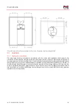
Page 15: ...eiling height must be 2100 mm The minimum room size must be 20 m 3 The heat pump is designed in such a way that it sucks in the air for ventilation through the pipe system from the room or from the surroundings The sucked in air emits its heat to the heat pump and is then depending on requirements you needs fed back into the selected room or into the surroundings The heat pump enables the followin...

Page 16: ...mplementation is that in which air is sucked in from rooms that are subject o a great deal of heat loss and is then directed to the heat pump which is usually installed in the cellar Some of the heat is extracted from this air and is then blown out back into the surroundings Air from bathrooms kitchens toilets etc frequently contain odours and are therefore blown out into the Austria Email AG id 1...

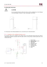
Page 17: ... How to connect the water pipe is shown in Figure 3 The maximum pressure in the water pipe must not be more than 6 bar The smooth pipe heat exchanger must be professionally flushed ugh before carrying out the initial installation in addition we recommend the installation of a dirt filter If the smooth pipe heat exchanger is not used during the operation of the storage tank e g HP only then this gl...

Page 18: ...mp There must be sufficient space above for the pipe channel connections The minimum distance to the walls must be 0 5 m The air piping system should be designed in such a way that on its way the air does not change the direction of its flow if possible The pipe length between the intake connection and the outlet connection should not exceed 10 m If the flow direction changes more often that must ...

Page 19: ...gths of more than 5 m the fan speed must be clamped to check the circuit diagram chapter 5 5 5 m 10 m 15 m 25 m For the final length of air ducts the equivalent length of accessories must also be considered equivalent length in m 3 2 1 2 Condensate drain connector Condensation forms in the thermal pump due to the humidity in the air Between 1 and 5 litres per day depending on the season and hot wa...

Page 20: ...ou use a siphon to prevent unwanted odours The condensation water drain must be designed in such a way that the condensate water can always drain off more easily The condensation water pipe must always be inclined downwards If this is not possible the condensation water must be channelled into a collector and the collector must be emptied regularly id 17 Austria Email AG id 17 14 35 1251 08 02 201...

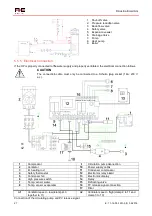
Page 21: ...he flow of condensation water Installation of the additional heating source The domestic water can be heated in various different ways The combination of heat pump and a boiler is called bivalent operation by means of which the water next to the living rooms is heated by the boiler o 1 Shut off valve 2 Pressure reduction valve 3 Back flow valve 4 Safety valve 5 Expansion vessel 6 Drainage Valve 7 ...

Page 22: ...operly ventilated the electrical connection follows The connection cable must only be connected to a Schuko plug socket 16A 9 Circulation pump connection 10 Power supply cable 11 Condenser compressor 12 Electronics relay board 13 Electronics display 14 Relay 15 Defrosting valve Temp sensor evaporator 16 PV release signal connection 17 Filter low clamp 2 3 n2 Ventilator speed high clamp 2 to 11 and...

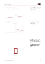
Page 23: ...elease signal cable through the guide at the back of the HP To insert the cable more easily spray the hose with a bit of soap 22 Pull the plug out of the wall to disconnect the power supply Remove the screws as shown in the image Remove the front cover Disconnect the controller keyboard and unplug the display cable Insert the circulating pump and the PV release signal cable through the guide at th...

Page 24: ...be completely filled with water after professional connection of the heat pump to the water network Only when the water exits without bubbles is the system properly filled and ventilated pump must never be operated without water this would risk causing damage to the compressor Austria Email AG id 17 14 35 1251 08 02 2016 Connect the circulating pump cable through the cable guide the circulating pu...

Page 25: ...e will be shown in the display The settings are displayed one after If the start sequence is not shown contact customer service If the heat pump is properly connected to the voltage and water supply after 2 seconds the control version of the operating programme selected or P1 appears on the screen as well as all parameters and their values 30 seconds after the electric connection the system starts...

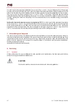
Page 26: ...am the PV photovoltaic signal however is also active and the water is heated to a higher temperature set temperature value set in L6 to max 65 C If the bivalent temperature is too low the water is heated with the e heating rod Note pressing the P key displays the programme selected the programme selected can also be checked using the flashing indicator see table above With each further press of th...

Page 27: ...ase of a radiator installed above 3 Water heating in the case of a PV release signal P6 The water is warmed up as in P5 until the set temperature has been reached If the PV equipment emits the release signal the water is heated to the set temperature plus the temperature rise parameter L6 up to a maximum of 65 C by means of the compressor The temperature rise is only active if the PV release signa...

Page 28: ...ameter description keys at the same time These two keys can then be used to scroll through the menu Select parameter L1 and after a few seconds the pre set switch off temperature to preparation of the set temperature this can be changed to any figure using the and 30 C 5 seconds after the desired setting the flashing stops and the settings are saved Uninstalling and disposal The device as a whole ...

Page 29: ...cuum cleaner to clean the fins or use air to blow out the fins Ensure that you do not damage the fin coils or other parts of the heat pump The evaporator fins are very sharp Please take care so as to prevent Checks before reporting damage to Customer Services Check that everything is in order with the electrical connecting lines Check whether the air outlet from the evaporator is obstructed by the...

Page 30: ...s not connected Connect the valve for the boiler heating circuit Circulation removes too much heat Switch off the pump and connect the circulation valve Somewhere in the system the gas pipe is leaking Phone the Customer Service Evaporator damage due to careless cleaning Phone the Customer Service HP runs constantly does not switch off Too little gas in the system Phone the Customer Service Circula...

Page 31: ...to the customer as repair and pro rata materials costs The illustrations and data are non binding and may be changed without comment in relation to technical improvements Subject to technical alterations errors and misprints excepted 7 In case of third party interference without our express instruction any and all claims shall be null and void even if this is done by a licensed installation techni...

Page 32: ...x 03512 700 239 Internet www austria email at E Mail office austria email at Austria Email in your area For addresses and telephone numbers of our subsidiaries visit our homepage at www austria email at Print errors and changes of all kinds are reserved Reproduction prohibited ...

Reviews: