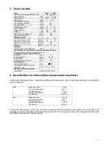
background image

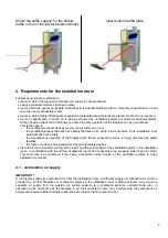
2.2 .  combustion air supply from the installation room 

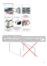
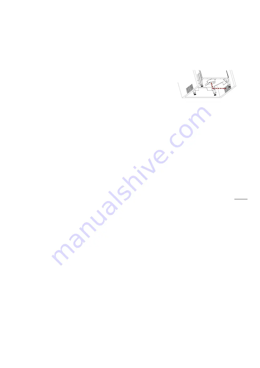
Austroflamm inserts obtain its combustion air only via the air connection collar at the bottom of the device. 
Therefore a structurally well functioning air supply into the combustion chamber must be ensured. For this 
purpose it is absolutely necessary to have the correct dimensioning of the convection air outlets and the 
necessary diameter of the combustion air inlets. The correct positioning of the mentioned in-/outlets into the 
fireplace is of major importance. A disregarding of the above may lead to a lack of combustion air during 
operation. In order to achieve a sufficient combustion air supply, we recommend to affix a closed conduct of air 
supply between the connection collar and the air inlet. 
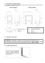
The external air flap collar of the models 80x64 and 97x74 is situated at left or right side of the carcass; all other 
models mentioned in this manual have the collar exiting at the bottom of the insert.  
 

Important! 

The connection collar should always be connected as described above,  
as  the sufficient air supply into the combustion chamber may 
otherwise not be ensured. 
 

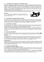
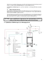
2.3.  combustion air supply with direct conduct 

The combustion air supply can also be set via a direct conduct from the outside to the insert. For this purpose the 
combustion air duct must be channelled from the external connection of the house directly to the fireplace. 
Please see the professional literature installation rules of the stove fitting trade to determine the diameter of the 
air conduct (see fig. 4.1 minimum diameters). In general this type of installation is recommended. 

2.4.  combustion air conduct 

Combustion air pipes must be made of non-inflammable, stable materials, their connection must be air-tight and 
the whole piping must be accessible for inspection and cleaning. The formation of condensate caused by a 
temperature fall below dew point shall be avoided by installing suitable insulation.  
According to the regional building regulations, combustion air pipes, which are to be installed in buildings with 
more than two full floors and combustion air pipes which are bridging firewalls, must be installed in such a 
manner, that fire and smoke cannot spread into other floors or fire compartments (see federal building 
regulations). 

2.5. chimney requirements 

The chimney must be inspected in terms of size and quality according to the existing local regulations 

before


positioning and installation of the Austroflamm insert (see applicable federal building regulations, fire prevention act 
as well as 
DIN 18160, part 1).  
A calculated proof of the sufficient function of the chimney according to DIN EN 13384 must be brought forth. 
The calculation must consider, that an essentially larger quantity of air can be exhausted safely if the door is 
open (reloading of fuel). The proper function of the insert depends on the connection to the correct chimney. 
Take care that all apertures leading to the same chimney, e.g. chimney cleaning flaps, are closed. 

 
Multiple allocation: 

All Austroflamm inserts described in this mounting instruction are also certified and approved according to DIN EN 
13229 with self-closing door (construction type A 1). Fireplaces, which will be operated with self-closing doors only, 
maybe connected to a multiply allocated chimney (if a multiple allocation is possible). The calculation has to be 
made according to DIN EN 13384 part 2. 

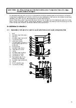
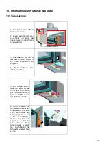
2.6.  connection pieces/flue pipe 

The flue pipes are to be rated according to DIN EN 13384. 
The flue pipes between the insert and the heat exchanger, as well as the piping into the chimney, must be made of 
steel, with a minimum wall thickness of 2 mm. Pipes made of austenitic or stainless steel only need a wall thickness 
of 1 mm. The flue pipe connection must be made directly into the chimney.  
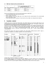
The flue pipes within the fireplace casing must be encased with minimum 3 cm stable and non-inflammable 
insulation material, category A1 according to DIN 4102, as described in the section insulation. This is not applicable 
for flue pipes which are meant for heating up the convection air and if a fire hazard can be ruled out. 


Summary of Contents for 45x51-aquaHEAT

Page 1: ...Mounting instruction 45x 65x aquaHEAT Austroflamm Inserts Mounting instruction aquaHEAT insert...

Page 2: ...w lzpumpensteuerung 12 7 4 Thermische R cklaufanhebung 12 7 5 Entl fter 12 7 6 Ausdehnungsgef 12 7 7 Wassermangelsicherung 13 8 Hydraulische Einbindung in das Heizungssystem 13 9 Erstinbetriebnahme un...

Page 3: ...efully BEFORE starting the installation All liability and warranty claims lapse for damages caused because of the non observance of this instruction Please also consider the guidelines given in the us...

Page 4: ...bearing capacity and adjust the legs with an allen screw SW24 see also 9 6 floor protection ATTENTION it is absolutely necessary to mind the guidelines for fire prevention like insulation and air gri...

Page 5: ...ing open door loosen both screws 2x Remove bracket securing 1 7 Assembly of baffle plates Unscrew the top baffle support on one side insert Keramott baffle plate and reassemble with the support by ref...

Page 6: ...allation room automatically and reliably the simultaneous operation of the fireplace with the air exhausting device is being prevented by safety facilities the fumes conduct is being supervised by spe...

Page 7: ...to the regional building regulations combustion air pipes which are to be installed in buildings with more than two full floors and combustion air pipes which are bridging firewalls must be installed...

Page 8: ...N EN 13229 CE approval Power water air kW 6 3 9 2 3 3 Ratio water air 66 34 74 26 Rated power kW 9 12 5 max operation pressure bar 3 max boiler temperature C 98 max log length cm 33 Allowed fuel quant...

Page 9: ...s Institut f r Bautechnik Berlin e g Promat Calciumsilikat W rmed mmplatte Promasil 950 KS Wolfsh her W rmed mmplatte Prowolf Wolfsh her W rmed mmplatte Vermilite 2000 Thermax W rmed mmplatte Thermax...

Page 10: ...sions ffnungen Luftgitter usw vorzusehen Der Betreiber der Anlage ist ausdr cklich ber die Sicherheitseinrichtung zu informieren Er muss in deren Funktion und Wartung eingewiesen sein Besonderer Hinwe...

Page 11: ...entil 3 TAS Tauchh lse mit Temperaturf hler 4 TAS Kaltwasserzulauf 5 TAS Sicherheitsw rmetauscher 6 TAS Ablaufleitung 7 Sicherheitsventil SV 8 Abblasleitung SV 9 Ablauftrichter Trichtersifon 10 Entl f...

Page 12: ...uf unkritische Temperaturen schlie t die TAS wieder selbstt tig Der Sicherheitsw rmetauscher der TAS ist getrennt vom Kesselvolumen oder Heizkreis Beim Ausl sen der TAS erfolgt kein ffnen der Heizkrei...

Page 13: ...h den Einbau ei ner Kesselladeeinheit Die Kesselladeeinheit dient zur Hochhaltung der R cklauftemperatur von Fest brennstoffkessel 7 5 Entl fter Entl fter sind bei einer Wartung zu pr fen und gegebene...

Page 14: ...N EN 12828 sind geeignete Ma nahmen vorzusehen Diese Ma nahmen m ssen gegebenenfalls bau seits innerhalb der Installation vorgesehen werden Jede geschlossene Heizungsanlage ist mit einem Wasserstandsb...

Page 15: ...is zum Ansprechen des SVs Dabei sollte der Ausl sedruck des SV nicht wesentlich ber oder unter 2 5 bar liegen 4 Nach der Funktionspr fung ist der Systemdruck zu berpr fen und gegebenenfalls auf den no...

Page 16: ...kochendes Wasser nicht ausreichend Installation instruction 9 1 Installation in front of or next to a wall which does not need extra protection 1 wall 2 insulation layer flue pipe 3 flue pipe 4 insul...

Page 17: ...assage 22 additional safety wall minimum 10 cm 9 3 Convection space If no convection cladding accessory is used a separate space for convection air A of minimum 6 cm between the insert and the insulat...

Page 18: ...bodens Aufstellb den 8 mit brennbaren Baustoffen m ssen wie folgt gesch tzt werden durch eine mindestens 6 cm Ma E dicke Betonplatte 7 die ber Aufstellb den ohne ausrei chende Querverteilung bewehrt s...

Page 19: ...rn entsprechend der H he des Feuerraumbodens ber dem Fu boden zuz glich 30 cm mindestens je doch 50 cm Nach den Seiten entsprechend der H he des Feuerraumbodens ber dem Fu boden zuz glich 20 cm mindes...

Page 20: ...ere Ausnehmung hin eingleiten 4 Die Senkschraube samt Platte abnehmen 5 Zum Schluss spannt man die Feder bis sie hinter dem Scharnierla ger einrastet und mon tiert die Platte wieder mit der Senkschrau...

Page 21: ...ag des Bol zens spannen 9 mm berstand 6 T r kann nun um 180 gedreht einbauen Umbau der Strahlungsbleche auf Rechtsanschlag ACHTUNG Die Glasleiste muss bei Rechtsanschlag um 180 in der T r gedreht werd...

Page 22: ...21 Demontage aller Teile Alle Laschen mit Schlitzschraubendreher aufbiegen Die Glasleisten f r die linke Montage einbauen und die Laschen mit der Zange zum Rahmen biegen Alle Teile wieder montieren...

Page 23: ...Aschenkasten 10 3 Feuerraum Die Keramott Einzelteile lose ohne M rtel in der abgebildeten Reihenfolge einlegen 1 Zugplatte 2 Zugplattenauflage oben 3 Holzf nger 4 Boden vorne 5 Boden links 6 Boden re...

Page 24: ...23 NOTIZEN Ausgabe 06 2010 Hersteller Austroflamm GmbH Austroflamm Platz 1 A 4631 Krenglbach...

Reviews: