background image

en/TA-11-ALM-6040/10040FL

pag.: 19

USER / 

INSTALATION

MANUAL

4-POST HD

ISSUED 26-05-04

A L M - 6 0 4 0 F L

A L M - 1 0 0 4 0 F L

AUTEC Hefbruggen bv

Industrieterrein IJsselveld, Vlasakker 11, 3417 XT MONTFOORT, The Netherlands

Tel: +31 348 477000   Fax: +31 348 475104 Internet: www.autec.nl - E-mail: info@autec.nl

6.

CHECKING THE MINIMUM REQUIREMENTS FOR THE PLACE OF 

INSTALLATION

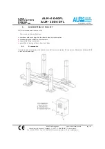
Check that the area in which the machine has to be installed has the tollowing characteristics:

=

enough light (without strong or dazzling lighting).

=

the area is not exposed to bad weather.

=

the area is adequately ventilated.

=

an unpolluted environment.

=

sound levels are below the prescribed standards required by law 

=

no dangerous movements are caused in the area by either machines being operated.

=

the area in which the machine is installed does not stock explosive, corrosive and/or toxic material.

=

the installation layout should be selected so that the operator can see all the equipment and the surrounding
area from the operating position. The operator must prevent unauthorised persons and potentially 
dangerous objects from entering this area.
All installation work concerning connections made to external power supplies (particularly electrical) should 
be done by professionally qualified staff.
Installation must be done by authorised staff following specific instructions where present in this manual: if 
in doubt, please consult authorised service centres or Autec technical services department.

Summary of Contents for ALM-10040FL

Page 1: ... 4 POST HD ISSUED 26 05 04 ALM 6040FL ALM 10040FL AUTEC Hefbruggen bv Industrieterrein IJsselveld Vlasakker 11 3417 XT MONTFOORT The Netherlands Tel 31 348 477000 Fax 31 348 475104 Internet www autec nl E mail info autec nl ELECTRO MECHANICAL FOUR POST LIFT ...

Page 2: ...under the terms of which the Equipment to which this manual relates was acquired or increases in any way Autec SUN VLT Equipment liability to the customer or to third parties To The Reader Whilst every effort has been made to ensure that the information contained in this manual is correct complete and up to date Autec SUN VLT Equipment reserves the right to change any part of this document at any ...

Page 3: ...device in the presence of obstacles 10 3 4 Mechanical block 10 3 2 Risk of damage due to electricity 11 3 3 Risk and protective media 11 3 4 Hazards associated with lifting of a vehicle 11 3 5 Risk for persons 11 3 5 1 Risk for the operator 11 3 5 2 Risk for personnel 12 3 5 3 Risk for impact 12 3 5 4 Risk for sliding out 13 3 5 5 Risk for electrocution 13 3 5 6 Risk due to insufficient lighting 1...

Page 4: ...ation 20 7 2 Assembling 21 7 3 Adjustment of the device controlling the wear of the support screw 27 7 4 Obstacle microswitch adjustment 29 8 INSTRUCTIONS FOR USE OF THE LIFT 30 8 1 IMPROPER USE OF THE LIFT 31 8 2 USE OF ACCESSORIES 31 8 3 STAFF TRAINING 31 8 4 IMPORTANT CHECKS TO BE MADE 31 9 MAINTENANCE INSTRUCTIONS 32 9 1 Motor chains 32 9 2 Containers at post base 32 9 3 Gear boxes 33 9 4 Angu...

Page 5: ...manual carefully before operating the lift since it contains important information concerning the safety of people safety of the lift safety of lifted vehicles G THE COMPANY IS NOT LIABLE FOR ANY POSSIBLE PROBLEMS DAMAGE OR ACCIDENTS ARISING FROM FAILURE TO FOLLOW THE INSTRUCTIONS 1 3 C o n t a i n e d i n t h i s m a n u a l The following is recommended for the proper use of this manual keep the ...

Page 6: ...subject G BEFORE USING THE LIFT MAKE SURE THAT THE MAINS POWER SUPPLY CABLE IS CONNECTED TO A MAINS POWER SUPPLY OUTLET OF THE CORRECT VOLTAGE WITH A PROTECTIVE EARTH CONTACT REFER SERIAL NUMBER PLATE ON THE UNIT FOR MAINS POWER REQUIRMENTS VOLTAGES HIGHER THAN SPECIFIED CAN DAMAGE THE UNIT AND MAKE IT UNSAFE G THE USE OF MAINS POWER SUPPLY EXTENSION CABLES IS NOT RECOMMENDED IF ONE HAS TO BE USED...

Page 7: ...LES THE LIFTING OF PERSONS OR USE AS SCAFFOLDING EXERTING PRESSURE LOADING G THE PRESENCE OF PERSONS INSIDE THE DANGER ZONE fig 1 IN THE SAME FIGURE IS STRICTLY PROHIBITED THE PRESENCE OF PERSONS BENEATH THE VEHICLE DURING OPERATIONS IS PERMITTED ONLY WHEN THE VEHICLE IS PARKED IN THE ELEVATED POSITION fig 1 The safety zone fig 1 is to some extend determined by the dimensions of the vehicle to be ...

Page 8: ...0 Kg 2 5 Pictograms on lift fig 2 IN THE EVENT OF THESE PICTOGRAMS BEING DAMAGED THEY MUST BE REPLACED BY NEW ONES AVAILABLE FROM Autec SUN VLT Equipment 1 OB904 09 7 OB901 ENSKA 3 OB904 10 8 OB901 DFSP 4 OB904 9 OB901 24000 5 OB905 EDNL 10 OB904 08 6 OB903 002 11 OB901 4000 Control unit en TA 11 ALM 6040 10040FL pag 8 ISSUED 26 05 04 ALM 6040FL ALM 10040FL AUTEC Hefbruggen bv Industrieterrein IJs...

Page 9: ...f persons under the vehicle is only permitted if the vehicle is parked and locked in the lifted position G USE THE LIFT ONLY IF ALL THE SAFETY ARRANGEMENTS ARE WORKING PROPERLY IF THESE RULES ARE NOT FOLLOWED SERIOUS INJURY COULD BE CAUSED TO PERSONS AS WELL AS IRREPARAIBLE DAMAGE TO THE LIFT AND THE VEHICLE ON THE LIFT 3 1 G e n e r a l p r e c a u t i o n s The operator is bound to follow the re...

Page 10: ... are released 3 3 S a f e t y d e v i c e i n t h e p r e s e n c e o f o b s t a c l e s If during lift descent an obstacle which resistance is greater than the weight of the moving element a special limit switch is activated causing the lift to halt in any working condition When the lift is at a halt the only pos sible command is the rise command which enables the obstacle to be removed followed...

Page 11: ...Leakage and breakage protection a pipe breakage valve has been fitted in the cylinder head that will in the event of pipe breakage reduce the rate of descenting of the tracks 4 Accoustic signal the lifting bridge will during its descent produce an accoustic signal 5 Lifting bridge locking next to the catch bar in each column a locking mechanism has been installed This consists of a strip in which ...

Page 12: ...ssured himself that there are no persons within the danger zone fig 4 3 5 3 Risk for impact Caused by parts of the lift or the vehicle that are positioned at head height When due to operational reasons the lift is immobilised at relatively low elevations less than 1 75 m from the ground personnel must be careful to avoid impact with parts of the machine not marked with special hazard colouring fig...

Page 13: ...lighting The area surrounding the lift must be properly lighted according to the legal requirements applicable in the place of installation 3 5 7 Risk of use maintenance Autec uses material of the highest quality in its lift These must be used according to the standard specified and maintenance must be carried out regularly 3 6 Suitability for use This product has been manufactured in compliance w...

Page 14: ...HD ISSUED 26 05 04 ALM 6040FL ALM 10040FL AUTEC Hefbruggen bv Industrieterrein IJsselveld Vlasakker 11 3417 XT MONTFOORT The Netherlands Tel 31 348 477000 Fax 31 348 475104 Internet www autec nl E mail info autec nl Place the vehicle in the centre of the footboards ...

Page 15: ...pment safely keeping in mind the dimen sions of the vehicle the weight the centre of gravity and protection of fragile parts 4 2 S t o r a g e The packed lift must always the placed in a covered area at a temperature between 10 o C and 40 o C and may not be exposed to direct sunlight 4 3 O p e n i n g t h e c r a t e s a n d b o x e s Check whether the machine hase been damaged during transportati...

Page 16: ...escribed on it 4 5 W a r r a n t y The warranty is valid for a period of 12 months starting from the date of the invoice The warranty will be automatically invalidated if unauthorised modifications to the machine or parts there of are carried out The Manufacturer s authorised personnel must verify defects in workmanship or materials 4 6 S e r v i c i n g For all servicing and maintenance operation...

Page 17: ...MANUAL 4 POST HD ISSUED 26 05 04 ALM 6040FL ALM 10040FL AUTEC Hefbruggen bv Industrieterrein IJsselveld Vlasakker 11 3417 XT MONTFOORT The Netherlands Tel 31 348 477000 Fax 31 348 475104 Internet www autec nl E mail info autec nl ALM 6040FL ALM 10040FL ...

Page 18: ...nl E mail info autec nl 5 DESCRIPTION OF THE LIFT LIFT Electromechanical four post lift Main technical specifications platforms with overhang at both sides for easy motor extraction mechanical synchronisation of movements irreversible lifting mechanism possibility of driving on down from both sides 5 1 C o m m a n d s Command cabinet containing the hydraulic control box mains switch lift rise butt...

Page 19: ...e prescribed standards required by law no dangerous movements are caused in the area by either machines being operated the area in which the machine is installed does not stock explosive corrosive and or toxic material the installation layout should be selected so that the operator can see all the equipment and the surrounding area from the operating position The operator must prevent unauthorised...

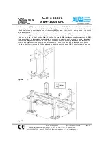
Page 20: ...tec nl E mail info autec nl 7 INSTALLATION 7 1 P r e p a r i n g t h e a s s e m b l i n g a r e a The lift must be placed on an even compact resistant floor If the floor does not meet these requirements construct 4 concrete bases fig 3 which must be cast at least a week before assembling the lift N B Concrete should be R bk 250 dass or higher with suitable reinforcement fig 12 Cement base measure...

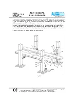
Page 21: ...cross pieces Check that the cross piece holes are turned inwards to let the control bar 12 through Check that cross pieces are both at the same height approx 650 mm from the underside of the cross piece to the upper surface of the post base plate If they are not remove cap 4 and fan 5 and turn the handwheel 6 locked on motor shaft 3 in the required direction until both cross pieces are at the same...

Page 22: ...UALL Y turn bar 12 just enough to allow an easy fitting Re fit the cases 9 fasten them with the appropriate screws Lead the gasket and the cable from the cross piece 1 into the welded tube on the footboard Remove the cover of the derivation box 16 where the cross piece cables enter 2 pass the cable from the footboard into the gasket attached to the derivation box Lead the gasket with cable inside ...

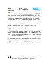
Page 23: ...TAN EP 220 210St OIL at 40 C ESSO or similar Electrical circuit connections The minimum power required is 25 kW Use the 10 mm2 cable for the main power supply Make sure that the motor voltage is the same as the main to change voltage from 220 to 380 Volts or vice versa change the con nections of both the 4 motors and transformer fig 6 W A R N I N G check that wires and terminals are matched to the...

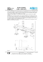
Page 24: ...es in the switch 21 input terminals Allow the lift to descend to the lower stop and fasten the four counter plates 26 to the floor by means of expansion nogs 27 supplied with the lift passing them through the diameter 25 holes in the counter plates Then put the posts in upright position fig 8 Loosen the screws 28 that fasten the adjustment device 29 Using a spirit level on the outside back and sid...

Page 25: ...t during the rise movement each pump pumps oil into the containers 19 Re fit the flaps 18 by using the screws 17 in all four posts Check that the obstacle safety switches work properly Check that the microswitches work by activating them manually The descent movement should halt Then operate the rise movement to raise the lift about 10 cm place a wooden wedge under cross piece 1 at a distance of 1...

Page 26: ... lf necessary adjust the limit switch 25 or its control cam Position the rise ramps 33 and fit the adjustable supports 34 lowering the adjustment screws 35 completely Check upper lower limit positions as follows press the rise button 22 and keep it pressed until upper limit stop is reached which is controlled by the limit switch 24 Use a straight edge as indicated above to check that the stop is b...

Page 27: ...TOR 3 Disconnect the fuses from motors no 1 2 4 and check that it operates correctly MOTOR 4 Disconnect the fuses from motors no 1 2 3 and repeat the test When you have identified the motor turning in the wrong direction invert two wires in the motor terminal board At this point you should make a complete rise and descent run with the lift fully unloaded to check that it oper ates correctly with a...

Page 28: ...ION MANUAL 4 POST HD ISSUED 26 05 04 ALM 6040FL ALM 10040FL AUTEC Hefbruggen bv Industrieterrein IJsselveld Vlasakker 11 3417 XT MONTFOORT The Netherlands Tel 31 348 477000 Fax 31 348 475104 Internet www autec nl E mail info autec nl fig 19 fig 20 ...

Page 29: ...per face of the wedge is in contact with the housing fig 13 pos B turn nut D clock wise about 1 10 of a turn and at the same time unscrew nut E anti clockwise Repeat this operation until both faces of the wedge fit into their housing always remembering to turn nuts D and E equally If the lower face of the wedge is in contact with the housing fig 13 pos C proceed as above but in reverse unscrewing ...

Page 30: ...itch 21 in position 1 RISE Press the rise button 22 DESCENT Press the descent button 23 EMERGENCY DESCENT WITH POWER SUPPLY OFF in the case of a power failure the lift may be lowered by two people operating as follows turn main switch 21 to position 0 remove the cover 4 and fan 5 from two diagonally opposite motors fit the relative handwheel 6 into the motordrive shaft Lock the hand wheel and turn...

Page 31: ...ed and authorised staff To ensure that the machine is used in the best possible way and work can be carried out efficiently the staff responsible for the machine must be properly trained to handle the necessary information in order to achieve an operative method in line with the instructions supplied by the manufacturer For any doubts concerning use and maintenance of the machine consult the instr...

Page 32: ...sen the four screws 4 inside box 2 by half a turn slacken locknut 5 and turn the screw 6 in the required direction After adjustment fasten the locknut 5 the four screws 4 of motor 7 and re fit the cover 1 9 2 C o n t a i n e r s a t p o s t b a s e fig 15 Every three months check the oillevel and top up where necessary as follows raise the lift with footboards to approximately one metre from the g...

Page 33: ...gs 42 To CHANGE THE OIL every 1 000 strokes or once a year remove the flaps also from the bottom of the cross pieces to reach the discharge plugs 9 4 A n g u l a r t r a n s m i s s i o n s Every six months remove level plugs 43 above the footboard 7 using a 6 mm hexagonal bar key Check the oil level and top up if necessary taking care not to exceed the maximum level Use a syringe to add or remove...

Page 34: ...3 2 mm If this is the case the load bearing support screw 1 should be replaced as the thread is almost completely worn If this check is not done the thread of the load bearing support screw 1 will wear through completely and the load will fall onto the counter screw 2 max stroke 10 mm The load resting on the counter screw 2 will unbalance the screws 5 which through the swing support to which they ...

Page 35: ...A heat control is disconnected Locking mechanism activated due to WEAR ON LOAD BEARING SUP PORTSCREW Obstacle under footboards and or cross pieces Burned transformer Faulty control switches Replace it Replace it Turn switch to position 1 Wait for the automatic reset of the heat control See MAINTENANCE INSTRUCTIONS section WEAR ON LOAD BEARING SUPPORT SCREWS See ASSEMBLING INSTRUCTIONS Replace it R...

Page 36: ...user RIF DESCRIPTION TERMINAL TR 50 VA TRANSFORMER TS RISE COMMAND CONTACT TD DESCENT COMMAND CONTACT STM1 4 MOTOR HEAT CONTROL FCUB1 4 LIMIT SWITCH FOR WEAR ON SCREW FCS RISE LIMIT SWITCH FCO1 4 OBSTACLE LIMIT SWITCH FCD DESCENT LIMIT SWITCH PS RISE BUTTON PD DESCENT BUTTON M1 4 MOTOR IG MAIN SWITCH FU6 SECONDARY PROTECTION FUSE TR SX20 3 15A 250 V RAPID FU5 PRIMARY PROTECTION FUSE TR 5X20 1A 250...

Page 37: ... dedaration applies is in compliance with the following standards and other normative documents EN 292 November 1992 pr EN 1493 rev n 10 EN60204 1 7 23 93 68 EMC 89 336 93 68 according to the provisions of the Directive 89 392 EEC 91 368 EEC 93 44 EEC 93 68 EEC Number of CE version Test Certificate 390 150X 0028 02 95 ALM 6040FL 390 150X 0029 02 95 ALM 10040FL issued by Bureau Veritas 34 reu Renne...

Reviews: