3 Recei
v
ing unit
- 12 -
LIMM&SA0-00.fm
3.3
Inner parts of the “Master/Master” receiving units
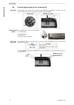
Mother board
The mother board in the receiving units is the E16B14AC.
Bus board
The receiving units URX-1 and URX-2 contain the bus board E16RI02D, where two radio receiv-
ing module have their seats; the one corresponds to the transmitting unit UTX-M and the other
to the UTX-S.
Position of the two radio receiving module is the one showed in the previous photo.
Frequencies set in the two radio receiving modules must undergo the following
rules:
- the radio receiving module corresponding to the transmitting unit UTX-M must
have the same working frequency as the transmitting unit UTX-M
- the radio receiving module corresponding to the transmitting unit UTX-S must
have the same working frequency as the transmitting unit UTX-S
See paragraph 8.4 to program the bus board E16RI02D.
3.4
General warnings for the installation of the receiving unit
FAILURE TO COMPLY WITH THE FOLLOWING WARNINGS MAR RESULT IN SERI-
OUS INJURY OR DEATH TO PERSONNEL AND DAMAGE TO EQUIPMENT.
Installation must only be carried out by qualified people and in accordance with
installation country rules.
The installer must always respect the following warnings:
Place the receiving unit vertically, with the cable gland (or plug) facing down.
Install the receiving unit so that the radio link is facilitated.
- the receiving unit must not be shielded by metal objects
- the antenna stylus must be at least 50 cm far from metal objects in its sur-
roundings
WARNING: If the receiving unit is covered by metal structures or installed inside
metal cabinets, use the appropriate extension kit for the antenna.
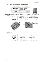
F1
POWER SUPPLY protection fuse
F2 and F3
STOP circuit protection fuses
F4 and F5
SAFETY circuit protection fuses
F1
F5
F3
F2
F4
Radio receiving module
corresponding to the UTX-S
Radio receiving module
corresponding to the UTX-M


