background image


43 

1)


Connect the scan tool to the vehicle’s DLC and erase the DTC(s) 
from the vehicle’s computer memory. (

See

 4.2 Erasing Codes

2)


After the erase procedure is performed, status of most monitors 
will  be  changed.  Leave  the  scan  tool  connected  to  the  vehicle, 
and select 

Ready Test

 from 

Main Screen.


3)


Keep on driving the car till the scan tool notifies you safely with 
color  LEDs  and  audible  tone  that  the  drive  cycle  has  been 
completed  and  the  vehicle  is  ready,  eliminating  drive  cycle 
guesswork and confirming readiness status. 

4)


If  the  GREEN  LED  lights  and  two  long  beeps  are  heard,  your 
vehicle is ready and the repair work is confirmed. 

5)


If the RED LED lights, your vehicle is not ready and the repair 
work is unsuccessful. 

As Pre-Check Diagnostic Tool 

Prior to having a vehicle inspected for compliance to a state emission 
test, you could use this function to check the readiness status first by 
yourself. 

1)


While the scan tool connected to the vehicle, select 

Ready Test


from 

Main Screen

. Drive the car till the scan tool notifies you 

safely with color LEDs and audible tone if your vehicle is ready 
to conduct state emission test. 

2)


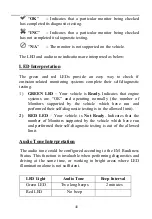
If  the  GREEN  LED  lights  and  two  long  beeps  are  heard,  your 
vehicle  is  ready  and  there  is  a  good  possibility  that  it  can  be 
certified. 

3)


If  the


RED  LED  lights,  your  vehicle  is  not  ready  and  must  be 

repaired before an emission test can be performed. 

Summary of Contents for 3912321514

Page 1: ...11 3 3 ACCESSORIES INCLUDED 11 3 4 NAVIGATION CHARACTERS 11 3 5 KEYBOARD 12 3 6 POWER 12 3 7 SYSTEM SETUP 12 3 8 ABOUT 20 3 9 VEHICLE COVERAGE 21 3 10 PRODUCT TROUBLESHOOTING 22 4 OBD II DIAGNOSTICS 24 4 1 READING CODES 25 4 2 ERASING CODES 28 4 3 LIVE DATA 30 4 4 VIEWING FREEZE FRAME DATA 31 4 5 RETRIEVING I M READINESS STATUS 32 4 6 VIEWING VEHICLE INFORMATION 38 4 7 EXITING THE OBD II TEST 40 5...

Page 2: ...n front of the drive wheels and never leave the vehicle unattended while running tests Use extreme caution when working around the ignition coil distributor cap ignition wires and spark plugs These components create hazardous voltages when the engine is running Put the transmission in PARK for automatic transmission or NEUTRAL for manual transmission and make sure the parking brake is engaged Keep...

Page 3: ...e Soon The system will also store important information about the detected malfunction so that a technician can accurately find and fix the problem Here below follow three pieces of such valuable information 1 Whether the Malfunction Indicator Light MIL is commanded on or off 2 Which if any Diagnostic Trouble Codes DTCs are stored 3 Readiness Monitor status 2 2 Diagnostic Trouble Codes DTCs OBD II...

Page 4: ...cated behind the ashtray and the ashtray must be removed to access the connector If the DLC cannot be found refer to the vehicle s service manual for the location Identifying specific malfunctioning section of the systems Systems B Body C Chassis P Powertrain U Network Code Type Generic SAE P0 P2 P34 P39 B0 B3 C0 C3 U0 U3 Manufacturer Specific P1 P30 P33 B1 B2 C1 C2 U1 U2 Sub systems 1 Fuel and Ai...

Page 5: ...icle depends on the motor vehicle manufacturer s emissions control strategy Continuous Monitors Some of the vehicle components or systems are continuously tested by the vehicle s OBD II system while others are tested only under specific vehicle operating conditions The continuously monitored components listed below are always ready 1 Misfire 2 Fuel System 3 Comprehensive Components CCM Once the ve...

Page 6: ...tus OBD II systems must indicate whether or not the vehicle s PCM s monitor system has completed testing on each component Components that have been tested will be reported as Ready or Complete meaning they have been tested by the OBD II system The purpose of recording readiness status is to allow inspectors to determine if the vehicle s OBD II system has tested all the components and or systems T...

Page 7: ...in Malfunction Indicator Light MIL Malfunction Indicator Light Service Engine Soon Check Engine is a term used for the light on the instrument panel It is to alert the driver and or the repair technician that there is a problem with one or more of vehicle s systems and may cause emissions to exceed federal standards If the MIL illuminates with a steady light it indicates that a problem has been de...

Page 8: ...code but also records a snapshot of the vehicle operating parameters to help in identifying the problem This set of values is referred to as Freeze Frame Data and may include important engine parameters such as engine RPM vehicle speed air flow engine load fuel pressure fuel trim value engine coolant temperature ignition timing advance or closed loop status 2 7 OBD II Modes of Operation Here is a ...

Page 9: ...gen sensor monitor screen and the test results gathered about the oxygen sensor There are ten numbers available for diagnostics 1 01 Rich to Lean O2 sensor threshold voltage 2 02 Lean to Rich O2 sensor threshold voltage 3 03 Low sensor voltage threshold for switch time measurement 4 04 High sensor voltage threshold for switch time measurement 5 05 Rich to Lean switch time in ms 6 06 Lean to Rich s...

Page 10: ...anufacturer specific Mode 09 Reports vehicle information This information includes vehicle VIN number and calibration information stored in the vehicle ECUs Mode 0A Requests emission related Diagnostic Trouble Codes with Permanent status This mode is required for all emissions related DTCs The presence of permanent DTCs at an inspection without the MIL illuminated is an indication that a proper re...

Page 11: ...ool to the vehicle s Data Link Connector DLC LCD DISPLAY Indicates test results GREEN LED Indicates that engine systems are running normally The number of monitors on the vehicle which are active and performing their diagnostic testing is in the allowed limit and no DTCs are present ...

Page 12: ...diness and drive cycle verification ENTER EXIT BUTTON Confirms a selection or an action from a menu Or returns to previous menu SCROLL BUTTON Scrolls through menu items USB PORT Connects the scan tool to the PC for upgrading 3 2 Specifications 1 Display TFT color display 220 x 176 dpi 2 Operating Temperature 0 C to 60 C 32 F to 140 F 3 Storage Temperature 20 C to 70 C 4 F to 158 F 4 External Power...

Page 13: ...C cover may be found for some vehicles and you need to remove it before plugging the OBD II cable 2 Plug the tool s OBD II cable to the vehicle s DLC 3 7 System Setup The scan tool allows you to make the following adjustments and settings 1 Language Selects the desired language 2 Configure Monitors Sets the monitors you want to test 3 Unit of Measure Sets the unit of measure to English or Metric 4...

Page 14: ...xit button Follow the instructions to make adjustments and settings as described in the above setup options Figure 3 2 Figure 3 2 Language Setup English is the default language 1 From System Setup screen use the SCROLL button to select Language and press the ENTER Exit button System Setup 1 8 Language Configure Monitors Unit of Measure Key Beep Set Status Beep Set ...

Page 15: ...n this menu you could configure the number of monitors to pass diagnosis and restore the default settings 1 Allowed INC Monitors From Configure Monitors screen use the SCROLL button to select Allowed INC Monitors and press the ENTER Exit button Emission tests vary depending on the geographic or regional area in which the vehicle is registered So the scan tool provides a more Language 1 3 English F...

Page 16: ...e Allowed INC Monitors will be set to 1 The tool will display an information message to ask for your confirmation Use SCROLL button to select Yes to proceed or No to exit without change Unit of Measure Metric is the default measurement unit 1 From System Setup screen use the SCROLL button to select Unit of Measure and press the ENTER Exit button 2 From Unit of Measure screen use the SCROLL button ...

Page 17: ...ion and return to previous menu Status Beep Set The default setting is Beep On This function allows you to turn on off the build in speaker for the LEDs in diagnostic testing Different audio tone corresponds to different LED lamp This function is invaluable when working in bright areas where LED illumination alone is not sufficient 1 From System Setup screen use the SCROLL button to select Status ...

Page 18: ...y A Display Test The Display Test function checks if the LCD display is working normally 1 From System Setup screen use the SCROLL button to select Tool Self test and press the ENTER Exit button 2 Select Display Test from Tool Self test menu and press the ENTER Exit button to start test Figure 3 8 Tool Self test 1 4 Display Test Keyboard Test LED Test Previous Menu Status Beep Set 1 2 Beep ON Beep...

Page 19: ...display If the key name does not show up then the key is not functioning properly Figure 3 9 The OK button refers to ENTER Exit button 3 Double press ENTER Exit to return to previous menu C LED Test The LED Test function verifies if the I M Readiness LED indicator lamps are functioning properly 1 Use the SCROLL button to select LED Test from the Tool Self test menu and then press the ENTER Exit bu...

Page 20: ...in www autel com to your computer 2 Run the MaxiLink II Tool Kit in your computer Figure 3 11 3 Connect the scan tool to your computer through the USB cable provided 4 From System Setup screen in scan tool use the SCROLL button to select Update Mode and press the ENTER Exit button 5 Select the programs to be updated in your computer There are two types of programs operating system and DTC library ...

Page 21: ... the aut file to update the DTC library Both the bin file and DTC file should be updated Otherwise the code reader cannot work properly When you made a wrong choice and the scan tool is unable to work properly you may need to update the programs To hold ENTER Exit button and power on the scan tool you will enter the Update Mode forcedly Then follow the update procedure to refresh the program To Ex...

Page 22: ...col Control Area Network CAN It is required by EPA that all 1996 and newer vehicles cars and light trucks sold in the United States must be OBD II compliant and this includes all Domestic Asian and European vehicles A small number of 1994 and 1995 model year gasoline vehicles are OBD II compliant To verify if a 1994 or 1995 vehicle is OBD II compliant check the Vehicle Emissions Control Informatio...

Page 23: ...the scan tool s OBD II connector is securely connected to the vehicle s DLC Verify that the vehicle is OBD II compliant Turn the ignition off and wait for about 10 seconds Turn the ignition back to on and continue the testing Verify the control module is not defective Operating Error If the scan tool freezes then an exception occurs or the vehicle s ECU Engine Control Unit is too slow to respond t...

Page 24: ...the I M Readiness test but the LED lamps are not working there may be several possible causes including bad connection and ignition off In this case follow these steps to check the scan tool Make sure the OBD II cable is connected to the DLC securely Verify the ignition key is in the KOER position Run the LED Test in the System Setup menu See 3 7 System Setup If the scan tool does not pass this te...

Page 25: ...re 3 1 6 Press the ENTER Exit button to wait for the Menu to appear A sequence of messages displaying the OBD II protocols will be observed on the display until the vehicle protocol is detected If the scan tool fails to communicate with the vehicle s ECU Engine Control Unit more than three times a LINKING ERROR message shows up on the display Verify that the ignition is ON Check if the scan tool s...

Page 26: ... module and press the ENTER Exit button to confirm 4 1 Reading Codes Reading Codes can be done with the key on engine off KOEO or with the key on engine running KOER Stored Codes are also known as hard codes which are fault codes or trouble codes that have been stored in the vehicle computer memory because the faults have reoccurred for more than a specified amount of key cycles These codes will c...

Page 27: ...ermanent Codes are DTCs that are confirmed and are retained in the non volatile memory of the computer until the appropriate monitor for each DTC has determined that the malfunction is no longer present and is not commanding the MIL on Permanent DTC shall be stored in non volatile memory and may not be erased by any diagnostic services or by disconnecting power to ECU 1 Use SCROLL button to select...

Page 28: ...eir definitions on screen Press ENTER Exit button to return to previous screen Figure 4 5 The control module number sequence of the DTCs total number of codes detected and type of codes Generic or Manufacturer specific Stored or Pending codes will be observed on the upper right hand corner of the display 4 If more than one DTC is found use the SCROLL button to check all the codes Read Codes 1 4 St...

Page 29: ... press ENTER Exit button to return to previous menu 4 2 Erasing Codes CAUTION Erasing the Diagnostic Trouble Codes may allow the scan tool to delete not only the codes from the vehicle s on board computer but also Freeze Frame data and manufacturer specific enhanced data Further the I M Readiness Monitor Status for all vehicle monitors is reset to Not Ready or Not Complete status Do not erase the ...

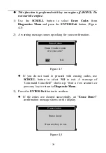
Page 30: ...ion Figure 4 7 If you do not want to proceed with erasing codes use SCROLL button to select NO to exit A message of Command Cancelled shows up Wait a few seconds or press any key to return to Diagnostic Menu 3 Press the ENTER Exit button to confirm If the codes are cleared successfully an Erase Done confirmation message shows on the display Figure 4 8 Erase Codes Erase trouble codes Are you sure Y...

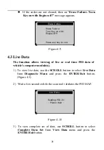
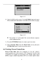
Page 31: ... data use the SCROLL button to select Live Data from Diagnostic Menu and press the ENTER Exit button Figure 4 3 2 Wait a few seconds while the scan tool validates the PID MAP Figure 4 10 3 To view complete set of data use SCROLL button to select Complete Data Set from View Data menu and press the ENTER Exit button Erase Codes Erase Failure Turn Key on with Engine Off Press any key to con Live Data...

Page 32: ...ious Menu from the Read Codes screen and press ENTER Exit button to return to previous menu 4 4 Viewing Freeze Frame Data Freeze Frame Data allows the technician to view the vehicle s operating parameters at the moment a DTC Diagnostic Trouble Code is detected For example the parameters may include engine speed RPM engine coolant temperature ECT or vehicle speed sensor View Data 1 3 Complete Data ...

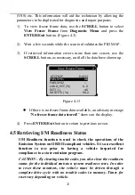
Page 33: ... No freeze frame data stored shows on the display 4 Press ENTER Exit button to return to previous screen 4 5 Retrieving I M Readiness Status I M Readiness function is used to check the operations of the Emission System on OBD II compliant vehicles It is an excellent function to use prior to having a vehicle inspected for compliance to a state emission program CAUTION By clearing trouble codes you ...

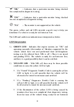
Page 34: ...Ready to pass the emission inspection OK Indicates that a particular monitor being checked has completed its diagnostic testing INC Indicates that a particular monitor being checked has not completed its diagnostic testing N A The monitor is not supported on that vehicle There are two ways to retrieve I M readiness status A Retrieve I M Readiness Status with One Click I M Readiness Key By simply p...

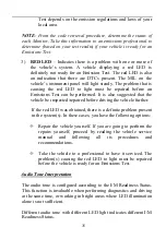
Page 35: ...diagnostic testing is in the allowed limit MIL is off There is no stored and pending DTCs The vehicle is ready for an Emission Test and there is a good possibility that it can be certified 2 YELLOW LED With MIL off there may be three possible conditions to cause the yellow LED to light If a Stored Diagnostic Trouble Code is causing the yellow LED to light it is still possible that the vehicle will...

Page 36: ...ggested that the vehicle be inspected repaired before driving the vehicle further If the red LED was obtained there is a definite problem present in the system s In these cases you have the following options Repair the vehicle yourself If you are going to perform the repairs yourself proceed by reading the vehicle service manual and following all its procedures and recommendations Take the vehicle...

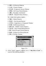
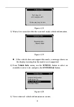
Page 37: ... I M Readiness from Diagnostic Menu and press ENTER Exit button Figure 4 3 2 Wait a few seconds while the scan tool validates the PID MAP 3 If the vehicle supports both types of tests then both types will be shown on the screen for selection Figure 4 15 4 Use the SCROLL button as necessary to view the status of the MIL light ON or OFF and the following monitors For spark ignition engines MIS Misfi...

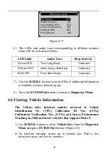
Page 38: ...or CCM Comprehensive Component Monitor EGR EGR System Monitor HCCAT NMHC Catalyst Monitor NCAT NOx Aftertreatment Monitor BP Boost Pressure System Monitor EGS Exhaust Gas Sensor Monitor PM PM Filter Monitor Figure 4 16 5 If the vehicle supports readiness test of This Drive Cycle a screen of the following displays Since DTCs Cleared 1 MIL Status OFF Misfire Monitor OK Fuel System Mon OK Comp Compon...

Page 39: ...turn to Diagnostic Menu 4 6 Viewing Vehicle Information The Vehicle Info function enables retrieval of Vehicle Identification No VIN Calibration ID Nos CINs Calibration Verification Nos CVNs and In use Performance Tracking on 2000 and newer vehicles that support Mode 9 1 Use SCROLL button to select Vehicle Info from the Diagnostic Menu and press ENTER Exit button Figure 4 3 2 An advisory message c...

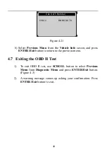
Page 40: ... the mode is not supported 4 From Vehicle Info menu use the SCROLL button to select an available item to view and press the ENTER Exit button Figure 4 20 5 View retrieved vehicle information on screen Vehicle Info 3 4 Vehicle ID Number Calibration ID Cal Verf Number Previous Menu Vehicle Info Reading info Please Wait Vehicle Info Turn key on with engine off Press any key to con ...

Page 41: ... return to the previous menu 4 7 Exiting the OBD II Test 1 To exit OBD II test use SCROLL button to select Previous Menu from Diagnostic Menu and press ENTER Exit button Figure 4 3 2 A warning message comes up asking your confirmation Press ENTER Exit button to exit Cal Verf Number CVN1 BB BA A0 78 ...

Page 42: ...d But how will you know when it is ready With this scan tool you don t have to drive around endlessly and continuously coming back to the repair shop for retest if all required tests by the ECU are completed And you could also do a quick check of the vehicle to determine if it is ready to receive an emission test without the hassle of connecting your vehicle to the analyzer or having to use a comp...

Page 43: ...ing diagnosis time and improving technician productivity Use the SCROLL button to select Ready Test from Main Screen Figure 5 1 and press the ENTER Exit button Figure 5 1 As Post Repair Diagnostic Tool This function can be used after the vehicle has done any emission related repairs to confirm that the repair has been performed successfully After repairs some drive cycles are required to reset the...

Page 44: ...icle is ready and the repair work is confirmed 5 If the RED LED lights your vehicle is not ready and the repair work is unsuccessful As Pre Check Diagnostic Tool Prior to having a vehicle inspected for compliance to a state emission test you could use this function to check the readiness status first by yourself 1 While the scan tool connected to the vehicle select Ready Test from Main Screen Driv...

Page 45: ... to INC condition In order to set these monitors to a Ready status the vehicle must be driven through a complete drive cycle Times for reset vary depending on vehicle Please refer to your vehicle s service manual for drive cycle information NOTE When using this function only the ENTER Exit button is available The other buttons are disabled to prevent misoperation 5 3 LED and Tone Interpretation Se...

Page 46: ...e systems are OK and operating normally the number of Monitors supported by the vehicle which have run and performed their self diagnostic testing is in the allowed limit 2 RED LED Your vehicle is Not Ready Indicates that the number of Monitors supported by the vehicle which have run and performed their self diagnostic testing is out of the allowed limit Audio Tone Interpretation The audio tone co...

Page 47: ...ct was altered or repaired by anyone other than the Manufacturer s Service Center 3 Autel shall not be liable for any incidental or consequential damages arising from the use misuse or mounting of the scan tool Some states do not allow limitations on how long an implied warranty lasts so the above limitations may not apply to you 4 All information in this manual is based on the latest information ...

Reviews: