10
ALTERNATOR OUTPUT TEST
F
This test accurately measures the maximum output of
the alternator under maximum load conditions. This
information provides the basis for further charging
system tests. It also detects the presence of an open
diode which causes an output loss of several amps
and can cause the failure of other diodes.
A FURThER LOOk...
ALTERNATOR TERMINALS
DELCO REMY- 10 SI
“BAT” = Alternator output to + battery.
“No. 1” = Battery current to rotor winding.
“No. 2” = Alternator output from battery.
DELCO REMY- 10 Dn
“Bat” = Alternator output to + battery.
“GRD” = Additional ground
“R” = Indicator lamp
“F” = Rotor winding to regulator
MOTORCRAFT
-Rear terminal
“BAT”= Alternator output to + battery
“STA” = Starter to various units including indicator lamp.
“FLO” = Rotor winding to regulator
“GRD” = Ground
SIDE TERMInAL:
Same except “STA” connects to rectified alternator
output.
CHRYSLER:
“BAT” = Alternator output to + battery.
“GRD” = Ground
(2) “FLD” = Connects to 2 insulated brushes
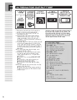
1. Tester hook-up see instruction “D” for hook-up.Turn
ignition on and read key draw before starting.
2. Start engine, idle at approximately 2000 rpm or to
manufacturers test rpm.
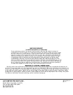
3. Slowly apply load. Adjust load to obtain maximum
alternator output on the amps scale. Do not allow
voltage to drop below 12 volts or 24 volts on 24
volt systems. Use vehicle accessories if necessary to
aid in applying load.
4. Check stator diode LED: If LED is on continuously, diode
or stator is bad. Replace alternator. A bad or “open”
diode or open stator windings can cause a slight drain
on alternator output as well as causing other diodes to
fail. This could eventually result in a failed regulator or
dead battery.
NOTE: LED may flash during transient loading, only a
steady light indicates a defect.
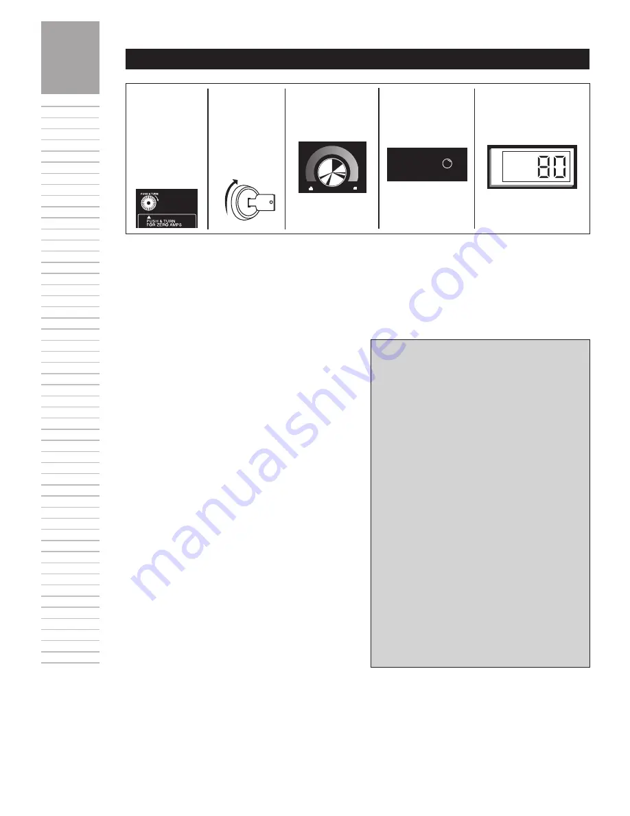
5. Read maximum amp output of alternator and remove
load. Add key draw reading to alternater output.
Output should be within 10-15% of manufacturers
specifications.
n
If output is O.K. go to voltage
REGuLATOR TEST
STEp H.
n
If output is low on the external regulator go to
REGuLATOR BYpASS TEST STEp G
n
If output is low on the internal regulator replace
alternator.
NOTE: Check alternator for correct size pulley. (Too large
may account for low output.)
n
Inductive Amp Probe in many cases might have to
be placed on the output wire of the alternator to read
maximum output.
STATOR
DIODE
A
M
P
S
1. HOOk-up
TESTER
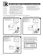
2. ZERO
AMMETER
(IF nECESSARY)
4. SLOWLY
AppLY LOAD
5. CHECk
STATOR DIODE
LED
6. READ MAX.
AMp OuTpuT OF
ALTERnATOR. THEn
TuRn OFF LOAD.
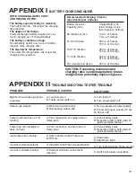
3. TuRn On
kEY AnD
READ kEY
DRAW (AMpS)
THEn START
EnGInE.
See “D” Tester Hook-
up
OFF
LOAD


