background image

5

 SAFETY


A

 INSPECTION


B

SAFETY PRECAUTIONS:

Carefully read all operating instructions before using.
Wear eye protection when working around batteries.
Load knob must be off before attaching or removing load clamps 

to prevent arcing and potential explosion.
Keep sparks, flames or cigarettes away from batteries.
Keep hair, hands, and clothing as well as tester leads and cords 

away from moving blades and belts.
Provide adequate ventilation to remove car exhaust.
In extremely cold temperatures, check for frozen electrolytic fluid 

before applying load.
Never connect large leads of this unit to more than a 12V battery.

Connection to 24 volts will dangerously overload the carbon pile 

and circuitry. To test 24 volt systems see “D”.

VISUAL ChECk


 Inspect and correct any frayed, glazed, cracked or 

loose belts; cracks in battery case; loose or broken posts; 

loose hold downs; low electrolyte level; corrosion on 

terminal; Wet area around terminals.

     Inspect starter, solenoid, and regulator for: Loose 

connections, loose mounting of components, and frayed 

or cracked wires.

STATE OF ChARGE


1. OPEN CELL BATTERIES- Using a hydrometer, 

check the specific gravity of the electrolyte fluid. Typical 

specific gravity values are as follows.


Reading Of: 

Indicates Battery Is:


1.265 


100% Charged


1.225 


75% Charged


1.190 


50% Charged


1.155 


25% Charged

These specific gravity values are applicable to an 

electrolytic temperature of 80°. The values must be 

adjusted for temperatures other than 80°, to do this: Add 

.004 for every 10 increments over 80°. Example: At 90° 

1.265 +.004 =1.269. Subtract .004 for every 10° under 

80°F. Example: at 70° 1.265 - .004 = 1.261.

     Specific gravity must be 1.225 or above. If low, charge 

per battery manufacturers specifications. Apply 

 a load equal to 1/2 cold crank amp rating for 5 seconds to 

remove surface charge.

     There should not be more than 50 points spread 

between cells. If more than 50 points, replace battery.

      2. SEALED TOP BATTERIES- (Maintenance Free) 

Battery must be at 12.4 volts or above before testing. If 

below 12.4, charge battery (See Appendix A) and apply 

a load equal to 1/2 cold crank rating load for 5 seconds 

to remove surface charge. Cold crank rating is explained 

under section “C” Battery Load Test. If battery reads less 

than 12.4 volts after recharging, replace battery. (6.2 volts 

for 6 volt batteries)

     IMPORTANT NOTE: A defective battery must be 

replaced before proceeding.

Valid automotive electrical system testing depends on 

all the components being in good operating condition. 

In addition, the battery MuST have sufficient charge 

for testing. Carefully perform the following before 

attempting any electrical diagnosis. 1. Visual Check 

and 2. State Of Charge.

A FURThER LOOk...

CAUSE OF BATTERY FAILURE.

1. INCORRECT APPLICATION: Wrong size battery 

may have inadequate cold cranking rating for 

original vehicle specifications.

2. INCORRECT INSTALLATION: Loose battery hold-

downs cause excessive vibration which can result 

in damage to the plates.

3. IMPROPER MAINTENANCE: Low electrolytic fluid 

and corrosion on battery connections, can greatly 

reduce battery life and affect battery performance.

4. AGE OF BATTERy: If the date code on the battery 

indicates it is fairly old, the failure may be caused 

by natural causes.

5. OVERCHARGING: Overcharging caused by a 

high voltage regulator setting or incorrect battery 

charging can cause excessive gassing, heat and 

water loss.

6. UNDERCHARGING Undercharging caused by a 

faulty charging system or low voltage regulator 

setting can cause lead sulfate to gradually build up 

and crystalize on the plates greatly reducing the 

battery’s capacity and ability to be recharged.

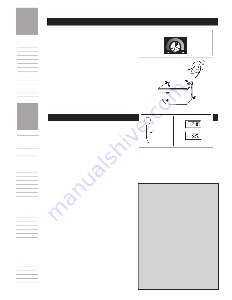
STATE OF CHARGE

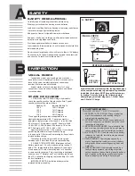
VISuAL CHECk

A. SAFETY 

Minimum 

1.225

See “C” for tester hook-up.

Inspect For: 

Frayed, glazed, 

cracked or loose belt.

OpEn CELL 

BATTERY

SEALED TOp BATTERY

Wet area 

around 

terminals

Corrosion on 

terminals

Loose hold 

downs

Loose or 

broken posts

OR

OFF

LOAD

V

O

L

T

S

V

O

L

T

S

Summary of Contents for BVA-34

Page 1: ... OPERATOR S MANUAL Quality Test Equipment Since 1957 ...

Page 2: ...System Overview 8 G Regulator Bypass Test Full Field 9 H Volt Regulator Test 10 I Amp Draw Test 10 J Voltage Drop Tests for starting systems 11 K Voltage Drop Tests for charging systems 12 Appendices I Battery Charging Guide 13 II Troubleshooting Tester Trouble 13 III Regulator Bypass Connections 15 Warranty and Service Information 30 CONTENTS Load Test Capacity 800 Amp Meters Two Digital 3 4 Char...

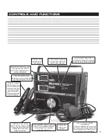
Page 3: ...econd maximum load time INDICATOR LIGHT when used in conjunction with the start timer button indicates when 15 seconds has elapsed VOLTS SELECTOR SWITCH switches volt reading from internal battery clamps to external volt leads COAXIAL CLAMP LEADS connects the unit to the battery and voltmeter for testing as well as provides power for the unit Red for positive and black for negative EXTERNAL VOLT L...

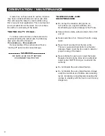
Page 4: ...ctive Amp probe on hot surfaces ie engine manifolds etc Overheating can cause damage to the Probe n Keep probe clamp surfaces clean free of dirt and oil n Keep leads free of oil Clean with warm soapy water n Never insert an object into the fan vents This can cause electrical and or mechanical damage Never cover the fan vents to allow for proper cooling of the tester n Never attempt to open up or r...

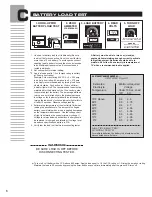
Page 5: ...between cells If more than 50 points replace battery 2 Sealed Top Batteries Maintenance Free Battery must be at 12 4 volts or above before testing If below 12 4 charge battery See Appendix A and apply a load equal to 1 2 cold crank rating load for 5 seconds to remove surface charge Cold crank rating is explained under section C Battery Load Test If battery reads less than 12 4 volts after rechargi...

Page 6: ...kwise Indicator light will turn off after 15 seconds Observe voltage reading 4 Estimate the temperature of the electrolyte fluid when reading the pass fail scale The amount of voltage a battery can maintain when a load is applied decreases as the temperature decreases Use the voltage chart at right to determine the correct minimum voltage If voltage level was below specifications battery should be...

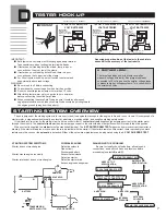
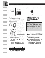
Page 7: ... when the ignition switch is turned to the start position When current is supplied the starter turns the crankshaft flywheel The E STARTER DRAW TEST measures how much current the starter is drawing If the starter draws too much current there is a problem with the starter If the starter draws too little current there is probably too much resistance in the circuit or the solenoid is defective Either...

Page 8: ...disconnecting it from the wiring harness On diesel vehicles Disconnect the fuel shut off solenoid On Ford Motor Company vehicles it may be possible to disable the inertia switch which is typically located in the trunks on cars and under the dashboard on trucks and vans n Check with manufacturer s proper procedure to disable ignition Improper method could cause damage to vehicles that are computer ...

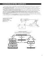
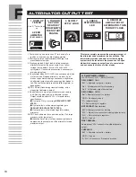
Page 9: ...ed in the G REGULATOR BYPASS TEST FULL FIELD to determine if low voltage is caused by the alternator or regulator The H VOLTAGE REGULATOR TEST should also be done to insure that the regulator is maintaining the proper amount of voltage after the car has warmed up Loose or corroded terminal connections and damaged or undersized wires can produce resistance which can cause the voltage to drop betwee...

Page 10: ...ator output on the amps scale Do not allow voltage to drop below 12 volts or 24 volts on 24 volt systems Use vehicle accessories if necessary to aid in applying load 4 Check stator diode LED If LED is on continuously diode or stator is bad Replace alternator A bad or open diode or open stator windings can cause a slight drain on alternator output as well as causing other diodes to fail This could ...

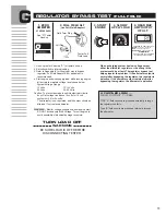
Page 11: ...engine and slowly apply load while running engine at fast idle to maintain voltage level shown below System Voltage Range 12 Volts 12 15 Volts 24 Volts 24 30 Volts Caution To prevent damage to vehicle electrical circuits do not let voltage rise above 15 volts for 12 volt systems or 30 for 24 volts The alternator is un regulated and full output should be attained If not replace alternator WARNING M...

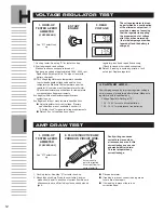
Page 12: ... voltage is within manufacturers specifications system is good If voltage is outside of manufacturers specifications n Adjust regulator to correct voltage If factory specifications are not available use chart in A Further Look for general voltage requirements n Retest If out of specifications check AMP DRAW TEST I Faulty wiring can cause current draw even when all accessories are off this current ...

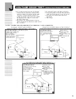
Page 13: ... INSULATED CIRCUIT TURN VOLT SWITCH TO EXTERNAL READ VOLTAGE DROP 24 VOLT SYSTEMS MUST BE CONNECTED TO A TEMPORARY 12 VOLT CONNECTION OVERALL STARTING SYSTEM TURN VOLT SWITCH FROM INTERNAL TO EXTERNAL Visually check for n Loose or corroded connections n Frayed or undersized wires n Bad contacts on the solenoid Visually check for n Loose starter mounting bolts n Bad battery ground terminal n Damage...

Page 14: ...f the tester 2 Set volt selector switch as indicated in the diagram 3 Hook up external leads to the part of the circuit being tested See following diagrams for specific hook up 4 Apply load by turning load knob clockwise Increase load until ammeter reads the manufacturers specification for alternator output 5 Observe voltage drop reading NOTE To check the overall charging system turn volts switch ...

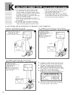
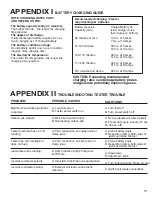
Page 15: ... 126 170 minutes 28 hrs at 5 amps 14 hrs at 10 amps 171 250 minutes 42 hrs at 5 amps 21 hrs at 10 amps 251 minutes and above 33 hrs at 10 amps PROBLEM Sparks when attaching clamps to battery Carbon pile steams Tester loads but has no volt reading Tester has volt reading but does not load Inaccurate amps reading Incorrect ammeter polarity Incorrect voltmeter polarity SOLUTIONS A Turn load off B Tur...

Page 16: ...ufacturer be responsible for special incidental or consequential damages or costs incurred due to the failure of this product Breaking the meter seal improper use accident water damage abuse unauthorized repairs or alterations voids the warranty The manufacturer disclaims any liability for consequential damages due to breach of any written or implied warranty on its tester WARRANTY SERVICE INFORMA...

Reviews: