9-9
FITTED EQUIPMENT
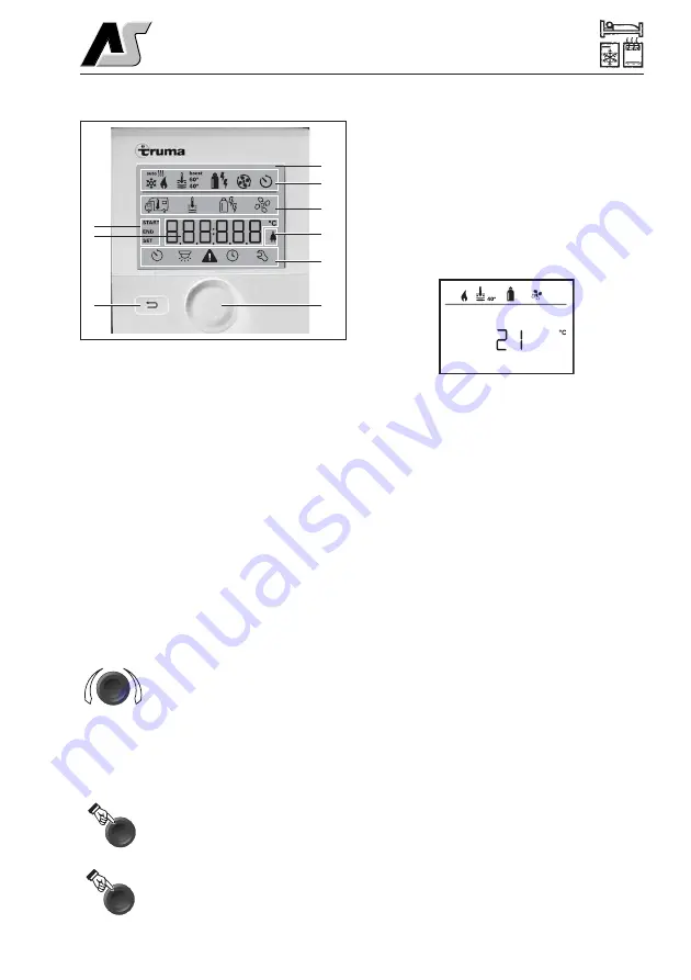
DISPLAY AND CONTROLS
1 = Display
2 = Status bar
3 = Menu bar (upper)
4 = Menu bar (lower)
5 = 230V mains supply indicator (power)
6 = Time switch display
7 = Settings / Values
8 = Rotary push button
9 = Back button
Menus can be selected in lines (3 + 4) using
the rotary push button (8) and settings made.
The display takes place using a screen (1)
with an illuminated background. The Back
button (9) can be used to return from a menu.
Rotary push button
Setpoints and parameters can be selected,
modified and saved by tapping on them using
the rotary push button (8). Selected menu
items flash.
Rotate right (+)
- Menu is run through from left to
right.
- Increase values.
Rotate left (-)
- Menu is run through from right
to left.
- Decreases values.
Touching
- Accept (save) a selected value.
- Select a menu item, switch to
setting level.
Press (3 seconds)
- Main switch function ON/OFF
.
Back button
Pressing the Back button (9) returns you from
a menu and discards settings. This means
that the previous values are retained.
Start-up
Start/standby screen
After connecting the control panel to the
mains power supply, a start screen is
displayed after a few seconds.
If no entry is made for several minutes, the
standby screen is automatically displayed.
Note:
If the time has been set (see “Set
time”), the display alternates between the
time and the room temperature setting. If no
time has been set, the room temperature
setting is displayed continuously.
Functions
The functions in the menu bars (3, 4) of the
control panel are selectable in any order. The
operating parameters are shown on the
status bar (2) and on the displays (5, 6).
Switch control panel on/off
-
Press rotary push button for longer than
3 seconds.
-
Previously set values / operating
parameters are reactivated after
switching on.
-
If the heating system or the air
conditioning system is without power for
more than 2 hours, the control panel
switches off automatically.
-
The control panel deactivation
procedures can be delayed by several
minutes because of internal heating
system after-runs.
2
3
5
4
8
6
7
9
1
+
-
3 sec
Summary of Contents for Topaz
Page 6: ...1 4 ...
Page 10: ...2 4 MOTORHOME CODE ...
Page 16: ...5 2 ARRIVAL AT SITE ...
Page 24: ...6 8 SAFETY SECURITY ...
Page 46: ...7 22 CONNECTION OF SERVICES 12V 230V WIRING DIAGRAM ...
Page 73: ...9 23 FITTED EQUIPMENT 1 2 4 3 5 6 ...
Page 74: ...9 24 FITTED EQUIPMENT 7 8 10 9 11 12 ...
Page 78: ...9 28 FITTED EQUIPMENT ARRANGEMENT OF EQUIPMENT TOPAZ ...
Page 82: ...9 32 FITTED EQUIPMENT NORMAL SEATING ASSEMBLY TOPAZ ...
Page 83: ...9 33 FITTED EQUIPMENT DOUBLE BED ASSEMBLY TOPAZ ...
Page 84: ...9 34 FITTED EQUIPMENT SINGLE BED ASSEMBLY TOPAZ ...
Page 106: ...12 10 SERVICE DETAILS ...
Page 108: ...13 2 NOTES Designed and Printed by Preset Graphics Tel 01332 549278 MY 2016 Ref 21465 ...


