background image


Installation Guide


P. 9


The Relay Connections 
85:
 Connects to the start module's trunk release wire output. This becomes the negative trigger for the coil. 
86: Connects to a fused +12 volt source.  
87: Connects to a negative source (where the remote start module is grounded). This becomes the supply for 
activating the vehicle's trunk release wire.  
87A: No connection. This terminal is not used in this application. 
30: Connects to the vehicle's trunk release wire. 
Comments: At rest the relay is not active and the vehicle's trunk release switch is allowed to operate normally. 
When the trunk release button is pressed, the start module's trunk release output activates the relay. The 
ground signal is sent from 87 through 30 to the vehicle's trunk release wire activating the switch and opening 
the trunk. 

Clutch


Bypass


In order to remote start a manual transmission vehicle, the clutch switch must be bypassed. Clutch safety 
switch circuits can take many forms. Listed below are the most common ones. When testing to determine the 
type of clutch circuit, it is recommended to use a computer safe logic probe. Some vehicles may also have a 
separate or combined switch on the clutch pedal for cruise control. Usually a cruise control switch reacts the 
moment you touch the pedal, where as a clutch switch reacts only when the pedal is near the floor. Once the 
circuit type has been determined, you must recreate what happens electrically at the switch, with the remote 
start module, to bypass the clutch during remote starts. Relays are often used to accomplish this. Always use 
the Ground Out When Running (G.O.) as the negative trigger on your clutch bypass relays, as it is only active 
during remote starts. NEVER permanently bypass a clutch switch. Do not attempt this if you are unfamiliar 
with the use of relays, and diode isolation.  
 
Before any Hot Wiring attempts:  
Test and record the way each wire tests in the following positions:  
With out the pedal pressed: 


Test the wires with the Ignition OFF 


Test the wires with the Ignition ON 


Test the wires with the Key in the start position 

With the pedal pressed: 


Test the wires with the Ignition OFF 


Test the wires with the Ignition ON 


Test the wires with the Key in the start position 

With this information for every wire at the switch, determining what type of clutch switching system you have will 
be easy. 
Direct Feed: 
The simplest type of system to test and bypass is the “Direct Feed” system. This circuit simply interrupts the 
+12v signal starter wire from the ignition switch to the starter solenoid. There are 2 wires in this circuit, the “key 
side” wire which goes from the clutch pedal to the Ignition switch, and the “solenoid side” which goes from the 
clutch switch to the starter motor. When the key is turned to the start position without pressing the pedal, you 
will test 12v only on one of the wires at the clutch switch, this is the key side. When the pedal is pressed down, 
and the key is in the crank position, the other wire will also read 12 volts; this is the solenoid side wire. To 
confirm you have a direct feed clutch switch, hot wire the “solenoid side” wire with a fused +12 volts and the 
starter motor will crank. Connect the starter output from the remote starter to solenoid side wire.  
Note: In the next two systems a Relay in the vehicle interrupts the start wire between the Ignition switch and 
the starter motor. With the key in the start position, and the clutch pedal pressed, the relay energizes and 
allows the start signal to reach the starter motor. In these systems a wires from the clutch triggers the relay, 
when the pedal is pressed. There will be another wire at the clutch switch that supplies the signal to the trigger 
wire (either positive or negative, depending on the system) 
Negative: 
 In a Negative system, when the clutch is pressed; a negative signal is sent to the relay, the relay energizes, 
when the Key is turned to the start position the 12volts from the start wire is allowed to pass through the relay 
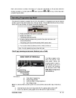
and to starter motor. One of the wires at the clutch will test as negative, this is the supply wire. The relay's 
negative trigger wire will only show negative when the pedal is pressed (some vehicle's also require the Ignition 

Summary of Contents for AS-6850TW-FM

Page 1: ...technician using all safety devices supplied Please note that this guide has been written for properly trained technicians a certain level of skills and knowledge is therefore assumed Please review th...

Page 2: ...ettings 21 Multi speed Tach Programming Procedure 21 Auto Tach Programming Procedure 21 Siren Horn Timing Adjustment 21 Setting the unit into Ready Mode 22 Arming and disarming of the System 23 Instal...

Page 3: ...x The following is a list of components included in the kit 1 Control unit 1 Plug in dual shock sensor 1 2 WAY LCD 6 button remote 1 Siren 1 1 WAY 5 button remote 1 Parts bag 1 Antenna and interconnec...

Page 4: ...ios where diode isolation is required Always make sure that any external relays or modules added to the Remote Starter module are properly fused and diode isolated When testing the Shock Sensor never...

Page 5: ...ftermarket grommet whenever you drill a hole through the firewall This will protect the wires from rubbing against the bare metal and possibly shorting out If you are installing an alarm starter combo...

Page 6: ...ted to either 87 or 87A What happens When there is no voltage across the coil terminals 85 and 86 the relay s movable contact arm connected to terminal 30 is held by spring tension against terminal 87...

Page 7: ...the 2nd ignition wire 87A NO CONNECTION This terminal is not used in this application 30 Connects to the vehicle s second ignition wire This becomes the output of the 2nd ignition relay Comments The r...

Page 8: ...o be disabled only when theft is attempted Solution A relay is used to interrupt the OEM starter wire There is an output on the remote start module especially for this purpose starter disable output T...

Page 9: ...s with the Ignition ON Test the wires with the Key in the start position With the pedal pressed Test the wires with the Ignition OFF Test the wires with the Ignition ON Test the wires with the Key in...

Page 10: ...rs the following is used to illustrate how these systems work in general A Relay is also used in these types of systems to interrupt the starter wire In the previous two examples the clutch was bypass...

Page 11: ...heater blower motor Use the 5th relay pin F and extra relays to power up any extra IGN wires if necessary DO NOT JUMP WIRES at the IGNITION switch this will compromise the OEM electrical system E ORAN...

Page 12: ...e Parking Light wire that tests 12 V when the Parking lights are ON NOTE Ensure that the voltage does not vary when the dimmer control switch is turned up or down If this is the case selected the wron...

Page 13: ...nserted in the Ignition switch and accidentally turned to the CRANK position The Starter Kill output becomes active during remote starts 8 ORANGE Parking Brake input This input is for manual transmiss...

Page 14: ...ust be added between the negative Glow plug trigger on the relay and the negative Glow plug wire of the car This is to prevent feedback effects on the Glow plug indicator light on the instrument clust...

Page 15: ...s of pins each set corresponds to a specific function of the output In order to activate one of the three possible functions you must place the jumper supplied on one of the three sets of pins and con...

Page 16: ...e handbrake wire is not connected to any of the vehicle circuits 3 Make all the regular connections 4 Power up the unit The parking lights will flash 4 times 5 When learning the first transmitter the...

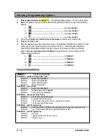
Page 17: ...lights are ON press the hood pin once more and release immediately The parking lights will turn ON and stay ON for 20 seconds You now have 20 seconds to select one of the sub menus Note To exit progra...

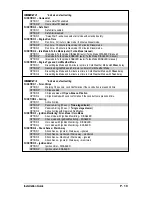
Page 18: ...function 2 of the mode selected and so on i for Option 1 ii for Option 2 iii for Option 3 iv for Option 4 Programming Options MODE 1 indicates default setting FUNCTION1 Ignition Controlled Door locks...

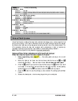
Page 19: ...e run time in Cold Weather Mode with 18sec delay OPTION 4 Diesel Engine Mode and 8 minute run time in Cold Weather Mode with 7sec delay MODE 3 indicates default setting FUNCTION 1 Siren Chirps OPTION...

Page 20: ...remote starter The VTS constantly monitors the data and readjusts itself automatically in order to maximize its capability to start the engine properly in any weather or deteriorating battery conditio...

Page 21: ...own until you hear the siren chirps 2 times 6 Release the brake pedal the tach programming is now complete Note If another Tach programming is required simply repeat the Multi Speed Tach learning Auto...

Page 22: ...stopped at any time The system will exit Ready Mode if a door the hood or the trunk is opened if the brake pedal is pressed if the parking brake is disengaged or if the ignition key is turned to the...

Page 23: ...r is left opened and the ignition is not turned ON 2 Active Mode a To arm the alarm press the button on the transmitter i The siren will chirp once ii The LED on the antenna will flash slowly b To dis...

Page 24: ...DOES NOT send an arm pulse while the engine is under remote start AUX 3 output This 500 mA negative AUX 3 output trunk output can be used for many different applications The output can be programmed...

Page 25: ...minutes 20 minutes by default Idle Mode Convenience feature Idle Mode allows you to keep the engine running and the doors locked while you stop for example at a convenience store or for a short deliv...

Page 26: ...nd remain lit The alarm and starter kill will be armed Press to unlock the doors and have the engine shut down after 60 seconds The parking lights will flash 3 times and remain lit Press To shut down...

Page 27: ...sec to warn the user that the vehicle was left unprotected Pressing or will cancel this timer Ignition monitoring Siren or Horn mode With this option the system can alternately be set to Siren mode o...

Page 28: ...operation Note See transmitter programming section on how to learn the transmitter to the second car Intrusion Codes via LED light The system monitors the following Any vibrations sensed by the shock...

Page 29: ...arking brake is active Yellow loop is connected 4 Brake wire is active 6 A tach signal is detected before Ignition 10 Hood wire is active Note The installer can also use the PRG 1000 to diagnose shutd...

Page 30: ...ations where they do not risk getting kicked or hit accidentally Most comebacks are the result of misunderstandings about how a product works or performs Take the time to properly explain all function...

Page 31: ...mitter against your chin will also increase your range your head acts as an antenna 8 The operating range will be somewhat lower on vehicles equipped with an aftermarket or factory alarm 9 Windows and...

Page 32: ...not the air conditioning system Missing second accessory common on some Fords 13 The CHECK ENGINE light comes on and the vehicle doesn t shift it feels sluggish Missing second ignition common on some...

Page 33: ...ota On some vehicles opening a door will shut the head lights off Pulse the drivers door pin with the rearm wire 23 I get no 12V reading at all at the brake pedal depressed or not Some vehicles requir...

Reviews: