4
v3.1 2428
The alarm is “Last door arming.”
You should diode isolate the inputs
of two or more sensors on the same
input wire.
If you choose not to use this alarm
feature then permanently ground this
wire or program “No Alarm” Option
#24 (section 24).
20. Red/Black Wire Diesel “wait to start” Control Harness
This wire is only used in diesel vehicle applications
– and is optional. This
wire can be hooked up to the “wait to start” light’s switched wire behind the dash.
If Option #9 (section 24) is set, this wire will feed information to the remote starter
as to when to crank the vehicle over. This wire is not polarity sensitive.
REQUIRED FINAL STEPS
Note: You must have hooked up all required wires and completed Initialization
(Step 11) to proceed forward.
21. Trying the Unit Out
WARNING: Be prepared to apply the brake during this testing.
A. Close the hood and fully apply the emergency brake
B. Place the vehicle in Park.
C. Turn the On/Off switch off then on – the red LED light will flash once.
D. Once all the wiring is checked and is correct, press the Start button on the
transmitter.
E. The car should start and continue to run for ten minutes. Make sure that the
engine shuts down if the car is shifted out of park, the hood is opened, the brake
is pressed or the start button is pushed again. If the car does not start, see
Special Cases.
22. The Antenna
Feed the antenna around under the dash and up the inside of the right or left
windshield post and over the top of the windshield. Clean the windshield
with the provided alcohol pad for maximum adhesion. Let the windshield dry
completely. Peel the liner off the back of the adhesive tape and mount the
antenna behind the rear view mirror. The more exposed the antenna is, the
better the range performance. Finally, plug the end of the antenna into the
remote starter module.
In most vehicles you will get better range perfor-
mance if the antenna is pointing vertically downward from the top of the
windshield.
Note: The wiring section of the installation is now complete. Be sure to
cap all unused wires so as to prevent short circuits, and mount the
module securely under the dash. When tying up and mounting the unit,
be sure to avoid any moving parts (steering column, pedals) and sharp
edges.
23. Trouble Shooting with the Self Diagnostics
The remote starter contains a built in diagnostic routine that will indicate why the
unit started or why the unit turned off the car the last time that the unit was used.
To activate the diagnostic mode for
why it turned off
, simply turn the On/Off
control switch to the “OFF” position. In a few seconds, the red LED light on the
module will flash 1 to 12 times to identify the problem. See the chart below for an
explanation of the flashes:
1
flash
10/15 minute time out. Unit should be fine. Make sure transmitter is
working properly.
2
flashes
Unit turned off because Brake or Hood was activated. Check to make
sure the hood pin switch is depressed when the hood is closed and
the correct brake wire is hooked up.
3
flashes
No Tach or Stalled. Review section 12 and make sure the no tach/tach
wire option is programmed correctly.
4
flashes
Received another remote input from the transmitter
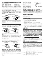
17A. Yellow and White – Keyless Entry Wires – 3 Wire Harness
The wires function as follows:
YELLOW
Negative Trigger – Unlock
Positive Trigger – Lock
WHITE
Negative Trigger – Lock
Positive Trigger – Unlock
Determine the polarity of your door lock system by using a test meter. For NEGATIVE
locks (the lock wire sees a ground signal briefly as the electric locks are locked) –
connect the YELLOW wire to the Unlock wire and the WHITE wire to the Lock wire.
For POSITIVE locks (the lock wire sees a +12 volt signal briefly as the electric locks
are locked but
does not see ground
when they are inactive) connect the YELLOW
wire to the Lock wire and the WHITE wire to the Unlock wire.
For REVERSING POLARITY (the lock wires sees a +12 volt signal briefly as the electric
locks are locked and
sees a ground
signal when they are inactive) follow the
diagram below:
To 12 Volt
Constant
(15 Amp Fused)
87
86
Lock Relay
White Wire
From
Remote Starter
3-pin Harness
85
30
87A
Vehicle Lock Wire
Cut
(Primary Switch Side)
(Actuator Side)
To 12 Volt
Constant
(15 Amp Fused)
87
86
Unlock Relay
Yellow Wire
From
Remote Starter
3-pin Harness
85
30
87A
Vehicle Unlock Wire
Cut
(Primary Switch Side)
(Actuator Side)
Reversing Polarity Door Locks
Most VACUUM operated door lock systems require Option #18 (section 24) for Long
locks to be set.
17B. Green Wire – Trunk Release – 3 Wire Harness
The GREEN wire is the Trunk Release output which gives out a transistor ground
output when the unlock button is held for 4 seconds.
Again, this is a 400 mA
transistor ground output which MUST drive a relay
(not included).
Negative Trunk Release
To 12 Volt
Constant
(15 Amp Fused)
Ground (-)
To Trunk Release
(in vehicle)
87
86
Green Wire
From
Remote Starter
85
30
87A
Positive Trunk Release
To 12 Volt
Constant
(15 Amp Fused)
To Positive
Trunk Release
(in vehicle)
87
86
Green Wire
From
Remote Starter
85
30
87A
18. Brown Wire – Accessory Pulse/Dome Light – Control
Harness
The BROWN wire is the Accessory Pulse output which gives out a momentary
transistor ground output 10 seconds after the vehicle is remotely started. This is
important in some vehicles to control the defroster or to control the GM R.A.P.
system.
Again, this is a 400 mA transistor ground output which MUST
drive a relay
(not included).
This BROWN wire can also control a relay for Dome Light activation. When Option
#20 (section 24) is changed, this BROWN wire causes the dome light to turn on for
25 seconds every time the doors are unlocked with the transmitter.
Negative Dome Light
To 12 Volt
Constant
(15 Amp Fused)
Ground (-)
To Negative
Door Pin
(in vehicle)
87
86
Brown Wire
From
Remote Starter
85
30
87A
Positive Dome Light
(Most Ford Vehicles)
To 12 Volt
Constant
(15 Amp Fused)
To Positive
Door Pin
(in vehicle)
87
86
Brown Wire
From
Remote Starter
85
30
87A
19. Red/White Wire – Door Pin Alarm Input – Control Harness
The RED/WHITE wire is the Door Pin Alarm Input. This wire will accept any input
that supplies a negative (ground) when activated. (Most door pins go to ground
when the door is open, +12 Volts when closed.)
Most Ford vehicles are positive door pins that switch to +12 Volts when opened, you
will need to reverse the polarity with a relay before connecting to this RED/WHITE
wire.
Positive Door Trigger
(Most Ford Vehicles)
Ground (-)
To Red/White Wire
from Remote Starter
87
86
Door Pin Switch
(in vehicle)
85
30
87A


