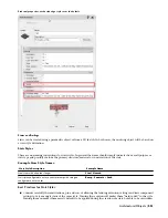
Layer Key Styles
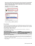
Layer Key Styles are the heart of an automated layer standard. There are several pre-defined Layer Key Styles provided
with AutoCAD Architecture that are based on existing widely accepted industry standards. You can also define your
own Layer Key Style.
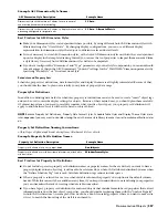
Layer Key Style Naming Conventions:
<Optional company name or other unique identifier> <Optional standard name> <Optional descriptive element>
Example Layer Key Style Names:
Example Name
Layer Key Style Description
BS1192
Layer Key Style based on the British BS1192 standard.
AIA v3
Layer Key Style based on the AIA Layer Guidelines version 3, with
provisions for deviation from Tri-Services plotting guidelines (using
named plot styles).
Company X Health Care
Layer Key Style created by “Company X” for use with their internal
layer standard, which is specifically used on medical projects.
Best Practices for Layer Key Styles:
■
Base your Layer Key Style on a structured AutoCAD Architecture Layer Standard, which defines the actual layer
naming format for your layers. Layer keys that are not based on a Layer Standard cannot take advantage of layer
key overrides.
■
Since Layer Key Styles define the color, line weight, line type and plot style for each layer they define, they should
work in conjunction with your display system. Before defining your own Layer Key Style, you should have a display
system in effect that has been tested and you should be very familiar with it.
■
Remember that several existing Layer Key Styles are already provided with AutoCAD Architecture. You may want
to start with these instead of creating a new one from scratch, modifying and adding layer keys as necessary to suit
your needs.
■
Don’t forget to specify, as part of your drawing settings the Layer Standard and Layer Key Style to automatically
load in any new drawing. Additionally you should specify that the Layer Key Style be reloaded in any existing
drawings if the “master” Layer Key Style in the library drawing has been edited recently. (Refer to “Template
Drawings” under the “Content Resources” section of this chapter).
Mask Block Definitions
Mask blocks are symbol-based style definitions that consist of a shape definition to serve as a masking object along
with optional additional graphics.
NOTE Mask blocks only affect AEC Objects and cannot mask generic AutoCAD objects such as lines, arcs, circles, etc.
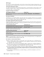
Mask Block Definition Naming Conventions:
Because Mask Block Definitions are symbolic objects, naming conventions are similar to those used for standard block
definitions. Since mask block definitions are best stored as AEC Content, you may also want the name to indicate the
category of AEC Content in which the mask block definition belongs:
Descriptive field>_<Optional descriptive field>_...<Optional size indication>
Example Mask Block Definition Names:
Example Name
Mask Block Definition Description
I_Elec_Lighting_Fluor_2x2
2’x2’ fluorescent lighting fixture for use in an imperial Architectural
project.
Company X_I_Furn_Table_Conf
Custom conference table created by/for “Company X” for use in
imperial projects.
Multi-Purpose Objects | 561
Summary of Contents for 00128-051462-9310 - AUTOCAD 2008 COMM UPG FRM 2005 DVD
Page 1: ...AutoCAD Architecture 2008 User s Guide 2007 ...
Page 4: ...1 2 3 4 5 6 7 8 9 10 ...
Page 40: ...xl Contents ...
Page 41: ...Workflow and User Interface 1 1 ...
Page 42: ...2 Chapter 1 Workflow and User Interface ...
Page 146: ...106 Chapter 3 Content Browser ...
Page 164: ...124 Chapter 4 Creating and Saving Drawings ...
Page 370: ...330 Chapter 6 Drawing Management ...
Page 440: ...400 Chapter 8 Drawing Compare ...
Page 528: ...488 Chapter 10 Display System ...
Page 540: ...500 Chapter 11 Style Manager ...
Page 612: ...572 Chapter 13 Content Creation Guidelines ...
Page 613: ...Conceptual Design 2 573 ...
Page 614: ...574 Chapter 14 Conceptual Design ...
Page 678: ...638 Chapter 16 ObjectViewer ...
Page 683: ...Designing with Architectural Objects 3 643 ...
Page 684: ...644 Chapter 18 Designing with Architectural Objects ...
Page 788: ...748 Chapter 18 Walls ...
Page 942: ...902 Chapter 19 Curtain Walls ...
Page 1042: ...1002 Chapter 21 AEC Polygons ...
Page 1052: ...Changing a door width 1012 Chapter 22 Doors ...
Page 1106: ...Changing a window width 1066 Chapter 23 Windows ...
Page 1172: ...1132 Chapter 24 Openings ...
Page 1226: ...Using grips to change the flight width of a spiral stair run 1186 Chapter 25 Stairs ...
Page 1368: ...Using the Angle grip to edit slab slope 1328 Chapter 28 Slabs and Roof Slabs ...
Page 1491: ...Design Utilities 4 1451 ...
Page 1492: ...1452 Chapter 30 Design Utilities ...
Page 1536: ...1496 Chapter 31 Layout Curves and Grids ...
Page 1564: ...1524 Chapter 32 Grids ...
Page 1611: ...Documentation 5 1571 ...
Page 1612: ...1572 Chapter 36 Documentation ...
Page 1706: ...Stretching a surface opening Moving a surface opening 1666 Chapter 36 Spaces ...
Page 1710: ...Offsetting the edge of a window opening on a freeform space surface 1670 Chapter 36 Spaces ...
Page 1956: ...1916 Chapter 42 Fields ...
Page 2035: ...Properties of a detail callout The Properties of a Callout Tool 1995 ...
Page 2060: ...2020 Chapter 45 Callouts ...
Page 2170: ...2130 Chapter 47 AEC Content and DesignCenter ...
Page 2171: ...Other Utilities 6 2131 ...
Page 2172: ...2132 Chapter 48 Other Utilities ...
Page 2182: ...2142 Chapter 51 Reference AEC Objects ...
Page 2212: ...2172 Chapter 52 Customizing and Adding New Content for Detail Components ...
Page 2217: ...AutoCAD Architecture 2008 Menus 54 2177 ...
Page 2226: ...2186 Chapter 54 AutoCAD Architecture 2008 Menus ...
Page 2268: ...2228 Index ...

