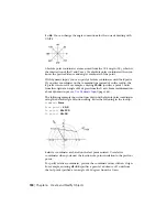
origin and its X, Y, and Z axes to suit your needs. The UCS is useful in 2D
design and essential in 3D design because it controls features that include
■
The XY plane (or work plane)on which objects are created and modified
■
The horizontal and vertical orientation used for features like Ortho mode,
polar tracking, and object snap tracking
■
The alignment and angle of the grid, hatch patterns, text, and dimension
objects
■
The origin and orientation for coordinate entry and absolute reference
angles
Understand the World Coordinate System (WCS)
The WCS is a fixed Cartesian coordinate system. Internally, all objects are
defined by their WCS coordinates, and the WCS and the UCS are coincident
in a new drawing. However, it is usually more convenient to create and edit
objects based on the UCS, which can be customized to suit your needs.
Understand the UCS Icon
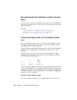
The UCS icon indicates the location and orientation of the current UCS. You
can manipulate the UCS icon using grips. For more information, see
The UCS
Icon
(page 24) and the UCSICON command.
NOTE
If the location of the UCS origin is not visible in a viewport, the UCS icon
is displayed in the lower-left corner of the viewport instead.
See also:
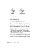
Control the User Coordinate System (UCS)
(page 131)
Work with Named UCS Definitions and Preset Orientations
(page 132)
Control the User Coordinate System (UCS)
Customize the UCS origin and orientation using the UCS origin and axes
grips, the UCS icon shortcut menu, or the UCS command.
You can align the UCS icon with existing objects, including 3D faces or edges.
Use Precision Tools | 131
Summary of Contents for 057B1-41A111-1001 - AutoCAD LT 2010
Page 1: ...AutoCAD LT 2013 User s Guide January 2012 ...
Page 20: ...zoom 553 xx Contents ...
Page 26: ...6 ...
Page 56: ...36 ...
Page 118: ...98 ...
Page 288: ...268 ...
Page 534: ...514 ...
Page 540: ...520 ...
Page 574: ...554 ...

