Create Splines Using Fit Points
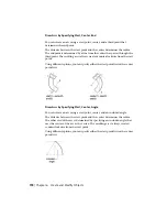
When you create splines using fit points, the resulting curve passes through
the specified points, and is influenced by the spacing of mathematical knots
in the curve.
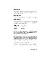
You can choose the spacing of these knots with the knot parameterization
option, which will result in different curves as shown in the example.
NOTE
There is no best choice for knot parameterization for all cases. The chord
length parameterization is commonly used, and the square root (centripetal)
parameterization often produces better curves depending on the data set.
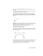
When the Tolerance value is set to 0, the spline passes directly through the
fit points. With larger tolerance values, the spline passes near the fit points.
Optionally, you can specify the tangent direction for the spline at each end.
NOTE
The fit point method always results in a degree 3 spline.
Special Cases
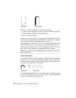
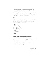
You can create a spline with a parabolic shape by specifying a degree 2 spline
created with exactly 3 control vertices as shown on the left. Degree 3 splines
188 | Chapter 6 Create and Modify Objects
Summary of Contents for 057B1-41A111-1001 - AutoCAD LT 2010
Page 1: ...AutoCAD LT 2013 User s Guide January 2012 ...
Page 20: ...zoom 553 xx Contents ...
Page 26: ...6 ...
Page 56: ...36 ...
Page 118: ...98 ...
Page 288: ...268 ...
Page 534: ...514 ...
Page 540: ...520 ...
Page 574: ...554 ...

