■
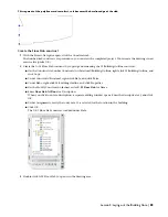
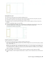
With Ortho on, move the cursor toward the top of the drawing.
■
Enter
1'
, and press ENTER.
■
Move the cursor to the right, enter
2'
, and press ENTER.
■
Move the cursor toward the bottom of the drawing, enter
1'
, and press ENTER twice.
The polyline is added.
10
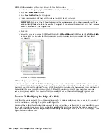
Select the lower wall of the enclosed space, right-click, and click Plan Modifiers
➤
Convert Polyline to Wall Modifier.
11
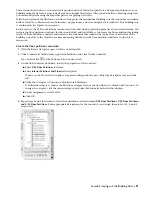
Select the polyline you sketched on the left construction line.
12
Enter
y
(Yes) to erase the layout geometry, and press ENTER.
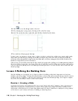
This erases the polyline sketch from the drawing and leaves the wall modifier.
13
On the New Wall Modifier Style Name worksheet, enter
Tutorial-Pilaster
for New Name, and click OK.
Naming the wall modifier style enables you to select the modifier from the worksheet on the Properties palette. In
the worksheet, you can remove the wall modifier, move it and reuse it at a different location along the wall. Use
a meaningful name, such as pilaster, so the wall modifier and its use makes sense to others.
14
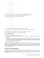
On the Add Wall Modifier worksheet, click OK to accept the default values.
This incorporates the wall modifier as part of the wall at a 0 elevation offset for both the starting and finishing
points. The polyline geometry defines the shape of the modifier that is added to the wall, and the modifier is
extruded to the full height of the wall.
The wall modifier (plan modifier) becomes an integral part of the wall.
98 | Chapter 3 Developing Your Building Model Design


