Lesson 1: Creating a Floor Plan, an Elevation, and a Section
When you are ready to present your designs, you prepare drawings to convey your ideas. You can create floor plans,
elevations, and sections. When you create floor plans, you can adjust the cut plane to control the display of your plan
view. When you prepare elevations and sections of your building model, you can add materials to the elevations to
give them texture, show additional detail, and illustrate the shape of building components more clearly.
For floor plans, you could use individual views drawings for each level that reference the appropriate constructs or you
can assemble a general view of the whole building and create view drawings. In this lesson, you create views for a floor
plan, section, and elevation from a general view of the whole building. You work with cut planes to control the floor
plan display, and you add materials to show additional detail in the section. You then see how the elevation is
automatically updated based on design changes made to the building model.
Exercise 1: Creating a View for a Floor Plan
The purpose of the floor plan is to show the location and dimensions of exterior and interior walls, windows, doors,
and other “fixed” features of the building model, such as stairs and elevators. The floor plan is actually a section drawing.
An imaginary cutting plane slices through the building model about four feet above the floor and parallel to the floor.
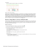
This exercise explores a three-dimensional (3D) general view drawing of the completed building model and shows how
to apply a cut plane. Cut planes are used to isolate building levels. The cut plane you apply in this exercise isolates level
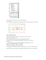
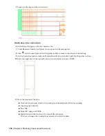
2, allowing you to visualize the floor plan of level 2. Then, you create a floor plan view for level 2 and modify the
display of the plan.
Explore a model view
1
With the Project Navigator open, click the Views tab.
2
Under Views\Exterior, right-click Model, and click Properties.
The Modify General View worksheet is displayed. The left pane shows the types of view properties that can be
customized, and the right pane shows the associated detailed information.
3
Click Context.
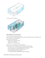
All the levels of the building model are selected to create a complete model view. Any constructs having an X-
prefix should be cleared. These are exercise files used to complete the specific tasks needed to complete the project
drawings.
138 | Chapter 4 Producing Construction Documents


