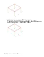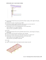
Justification lines meet to connect structural members
12
On the Structural Member Styles palette, right-click Roof Edge Assembly, and click Apply Tool Properties
to
➤
Linework.
13
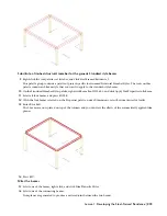
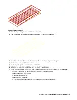
Select the four outer lines of the grid, and press ENTER.
14
On the Convert to Beam worksheet, verify Erase Layout Geometry is cleared, and click OK.
You use the retained linework in a later step to create the floor.
15
With the beams selected, set the following properties on the Properties palette:
■
Under Dimensions, select Baseline for Justify.
■
Under Location, enter
10'2-1/8''
for Elevation.
16
Press ESC.
17
On the Structural Member Styles palette, right-click Beam Roof W12x5.5, and click Apply Tool Properties
to
➤
Linework.
18
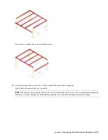
Select all thirteen of the inner lines in the drawing, and press ENTER.
19
On the Convert to Beam worksheet, verify Erase Layout Geometry is clear, and click OK.
20
With the beams selected, set the following properties on the Properties palette:
■
Under Dimensions, select Middle Center for Justify.
■
Under Location, enter
10'2-1/8''
for Elevation.
21
Press ESC.
22
Click
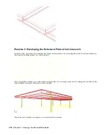
on the Views flyout on the Navigation toolbar to display the model.
Lesson 1: Developing the Steel-Framed Residence | 221


