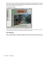
background image

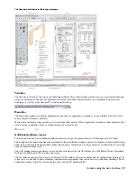
The Design tool palette

Three default tool palette groups - Design, Document, and Detailing - provide instant access to a complete inventory
of Architectural Desktop tools. The three tool palette groups correspond to stages in the architectural design process
and contain palettes that feature relevant tools. For example, the Design palette group contains Design, Massing, Walls,
Doors, and Windows palettes. You might use the Design palette, which features objects with standard styles only, in
your early design stage, and then use tools from the Walls, Doors, and Windows palettes to convert the objects to
specific styles later in the project. To display all the tool palettes from the available tool palette groups, click the title
bar of the tool palettes set, right-click, and click All palettes.

All Design, Document, and Detailing palettes

You can add tool palettes to tool palette groups from a tool catalog in the Content Browser, a utility where you can
store, share, and exchanges tool and tool palettes.You can create custom tool palettes that address your specific design
needs, like a palette that stores commonly used curtain wall, stair, and window tools. Tools can be organized on palettes
with separators and text to structure large palettes.

Understanding the User Interface | 23

Summary of Contents for 18506-091462-9305 - Architectural Desktop 2006

Page 1: ...AUTODESK ARCHITECTURAL DESKTOP 2006 Imperial Tutorials Update August 2005 ...

Page 2: ...ign Doctor Designer s Toolkit DesignProf DesignServer Design Web Format DWF DWG Linking DXF Extending the Design Team GDX Driver gmax logo gmax ready logo Heads up Design IntroDV jobnet ObjectDBX onscreen onair online Plans Specs Plasma PolarSnap ProjectPoint Reactor Real time Roto Render Queue Visual Bridge Visual Syllabus and Where Design Connects Autodesk Canada Inc Trademarks The following are...

Page 3: ...ettes 22 The Properties Palette 24 Content Browser 25 DesignCenter 26 Detail Component Manager 27 Arranging Your Workspace 27 Chapter 2 Getting Started with Projects 29 Understanding the Tutorial Project 30 Lesson 1 Setting up the Small Office Building Sample Project 30 Exercise 1 Exploring Project Drawings 30 Exercise 2 Creating a Set of Project Tools 37 Lesson 2 Setting up Your Project Template ...

Page 4: ... View for a Floor Plan 138 Exercise 2 Using Callouts to Create a 2D Elevation View 144 Exercise 3 Changing Materials Within an Elevation 146 Exercise 4 Modifying and Updating a 2D Section 149 Exercise 5 Creating a 3D Section 151 Lesson 2 Working with Details 155 Exercise 1 Using the Detailing Tool Palettes 155 Exercise 2 Using Detail Component Manager 159 Exercise 3 Modifying Details 164 Exercise ...

Page 5: ...r a Screen 239 Lesson 3 Sharing Design Data 242 Exercise 1 Creating a Terrain Model 243 Exercise 2 Analyzing the Site for Flooding 251 Exercise 3 Creating Elevations for a Sheet 257 Exercise 4 Updating Elevations 262 Exercise 5 Creating a Section for a Sheet 263 Exercise 6 Updating a Section 267 Exercise 7 Publishing Model and Detail Views to 3D DWF 273 Lesson 4 Updating and Modifying Project Tool...

Page 6: ...iv Contents ...

Page 7: ...creation and publication of construction documents In the second section of the tutorial which focuses on creating a project you work with a small office building dataset In the third and fourth sections you develop and document the design of the small office building using the same dataset you used previously You can follow the workflow presented in these lessons when you start your own projects ...

Page 8: ...r knowledge of AutoCAD If you are not familiar with basic AutoCAD functions and commands see the online AutoCAD 2006 User s Guide Printing theTutorial If you want to print all or part of this tutorial you can access and print the tutorial PDF adt_itut_2006 pdf located on the product installation CD in root ADT Docs To open view search and print the PDF you must have the free Adobe Reader installed...

Page 9: ...her than the default location when prompted to re path the project click Yes 13 Click Close to close the Project Browser 14 On the Project Navigator click the Project tab 15 Under Current Project verify that Name displays the correct project for example Small Office Building_I To change the current project double click another project name in the Project Browser and repeat steps 13 through 16 16 K...

Page 10: ...semble the 3D building model The 3D model not only represents the physical building but also stores information about the building and its components When you have developed the building model enough to begin documenting it you can extract drawings such as elevations and sections from the building model and reference them onto plotting sheets The benefit of this object based design approach is tha...

Page 11: ...l to understand some of the main features in Autodesk Architectural Desktop that allow you to work with the architectural objects included in the application The following example demonstrates how to draw a wall that includes a door To draw the wall you select a wall tool from a tool palette A wall tool on a tool palette Tools are commands that you use to draw objects Tools take the form of icons ...

Page 12: ...operties such as the width or base height of the wall before you draw the wall The Properties Palette Before you specify the start point of the wall you can use the drawing aids on the application status bar to help you control how the wall is drawn To draw this short straight wall segment you want to click to constrain your cursor to move only in a horizontal or vertical orthogonal direction afte...

Page 13: ...in Architectural Desktop You can also create your own office layer standard The style of the wall determines what type of wall is being drawn A style is a set of parameters that you apply to an object to determine its appearance or function For walls styles contain components which are the materials used to construct the wall such as brick CMU concrete studs air gaps and insulation They also can c...

Page 14: ...individual display components within a display representation The properties of each component such as visibility layer linetype and lineweight can be configured in the display representation to change how the object displays in a drawing Display components in the Plan display representation of a wall 8 Chapter 1 Introduction ...

Page 15: ...n sets assigned to view direction The drawing is a volume cube with representation sets assigned to the viewing direction Drawing templates provided with Architectural Desktop contain display settings that you use to easily manage the display of objects in your drawings created from these templates They also associate particular layer standards and layer key styles to drawings Object styles are no...

Page 16: ... The door also has grips that enable you to flip the door swing to the other face of the wall or reverse its direction Grip editing a wall and door If you move your cursor over a grip a grip tip displays the name and function and function of the grip Often the grip tip lists editing options A door grip tip Moving the wall with its location grip will also move the door This inter relationship betwe...

Page 17: ... building in the project The project file structure is created when you create a project There is no need to set up a file structure for the project in Windows Explorer Two UI elements within Architectural Desktop the Project Browser and the Project Navigator palette provide access to your projects and the drawings organized within them The Project Browser lets you create set up and switch between...

Page 18: ...all levels of the project making it span the height of the building This type of construct is called a spanning construct The construct s level and division assignments define its exact location in the building model A lighting construct assigned to its location in the building A spanning construct drawn to span several floors and assigned to the floors levels Elements are collections of geometry ...

Page 19: ... updated in the sheets because the building model drawings are referenced into the views on the sheets You can add annotation like tags dimensions and schedule tables to a sheet or you can add it in a view that you reference onto a sheet Whether to create the annotation in a view or on a sheet is a decision you make based on your workflow and individual needs Each project contains a single sheet s...

Page 20: ...es in the geometry or material of the Architectural Desktop model into VIZ Render for as long as you retain the file link Next depending on the type of visualization you want to create with VIZ Render you can make changes and additions to the design in VIZ Render Although you cannot model in VIZ Render you can rearrange objects modify their materials and add lighting cameras and additional objects...

Page 21: ...rials accessible from the VIZ Render Help menu Understanding the User Interface Autodesk Architectural Desktop includes two distinct user interfaces the workspace and the VIZ Render user interface The workspace is displayed when you start Architectural Desktop The workspace and its components support you through your project workflow allowing you to move seamlessly from creating a project and desi...

Page 22: ...Z Render from the VIZ Render icon on your desktop The VIZ Render user interface The topics in this section describe the workspace and its components To learn about the VIZ Render user interface see the VIZ Render Help and Tutorials accessible from the VIZ Render Help menu The Workspace Before you begin the tutorial it is helpful to understand the workspace and some of its main components Use the i...

Page 23: ...nal pulldown menus You can load and use four additional pulldown menus Design Documentation CAD Manager and 3D Solids The Design and Documentation menus are similar to those included in releases prior to Autodesk Architectural Desktop 2004 in that they include design and documentation object commands Use these menus as an alternative to accessing object commands from tools The CAD Manager menu pro...

Page 24: ...oom view UCS and shading commands Shapes toolbar 2D object commands such as lines arcs polylines splines Standard toolbar drawing copy paste undo and regenerate model commands To display additional toolbars right click in the toolbar area not on a toolbar and click ADT A menu lists the toolbars that you can click to display If you load the 3D Solids CAD Manager Design and Documentation pulldown me...

Page 25: ...h Toggle Layer Key overrides the Isolate Objects command that hides and displays objects that you select and access to AEC Project Standards To display and clear these options from the drawing window status bar click and click the options that you want to display or clear To display and hide the drawing window status bar click on the application status bar at the bottom of your screen Open Drawing...

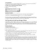
Page 26: ...ally You use it to create edit and manage the drawings within the project The Project Browser To display the Project Browser On the File menu click Project Browser On the Navigation toolbar click To configure the Project Browser to display when you start Architectural Desktop click Format Options Click the AEC Project Defaults tab and select Show Project Browser at startup In the Project Browser y...

Page 27: ...and sheets The Project Navigator contains four fixed tabs that correspond to the main phases of a building project The Project tab contains the project information including the levels and divisions in the building model a Content Browser icon that will open a project specific library of tools and a link to configure project standards The Constructs tab manages the construct and element drawings t...

Page 28: ... drawings typically of an element to a construct a construct to a view and a view to a sheet enhance drawing coordination An update to a construct in a project such as a floor plan is automatically passed along to a view of an annotated floor plan and a sheet containing the scaled view Notifications of changes are sent to project team members as the drawings change so team members can update any o...

Page 29: ... Walls Doors and Windows palettes to convert the objects to specific styles later in the project To display all the tool palettes from the available tool palette groups click the title bar of the tool palettes set right click and click All palettes All Design Document and Detailing palettes You can add tool palettes to tool palette groups from a tool catalog in the Content Browser a utility where ...

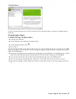
Page 30: ...ates to create other projects Creating projects from these template projects lets you create projects that have custom tools palettes and content ready for use at the inception of a new project The Properties Palette To display the Properties palette Select a tool On the Window menu click Properties Palette On the Navigation toolbar click Select an object right click and click Properties Press CTR...

Page 31: ... now available as tools stored in the Content Browser A tool catalog can contain tools tool palettes and tool packages collections of tools Tool catalogs are placed in catalog libraries A Content Browser library can be set up on a shared network volume to be accessed by all users in a specific project The CAD manager or project owner can point the project to that Content Browser library to have qu...

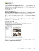
Page 32: ...m or drawings on a network A library of AEC architectural engineering and construction content included in Architectural Desktop is accessible through the DesignCenter Four tabs in the DesignCenter Folders Open Drawings AEC Content and DC Online offer access to content in the different locations You can also access content on web pages with DesignCenter Online DesignCenter Online provides access t...

Page 33: ...om the Detail Component Manager onto a tool palette to create detail tools The Detail Component Manager When you define or change project settings you can specify the detail component database s that you want to use to create project details ensuring that all project team members use components from the same databases Two detail component databases are included with Architectural Desktop one US sp...

Page 34: ... bar and click Allow Docking Then drag the palette to either side of the window You can lock and unlock palettes with the same option that you use to lock and unlock toolbars To control the size and listing of tools on palettes right click on a palette and select View Options You can size the tools as appropriate for your screen resolution and workspace arrangement After you arrange your workspace...

Page 35: ...g many drawing files Drawing Management formalizes and automates the organization and management of external reference files letting you work with the logical pieces of a building as opposed to managing the file system In this part of the tutorial you are introduced to the key concepts of Drawing Management as you begin the design development phase of a sample commercial building project 29 ...

Page 36: ...e organized and managed in a project environment This introduction focuses on the fundamental information you need to be successful as you begin your work with projects For in depth coverage of project related topics use the cross references provided throughout the lesson Finally you create a new project which forms the basis for future work You create a project template with project standards sty...

Page 37: ...hich to work TIP Use the drop down list for the project folder location to browse to the installed projects The Small Office Building project by default is installed to my documents autodesk my projects If you are using Architectural Desktop in a network environment the tutorial files may have been installed in a different location Contact your network administrator or CAD manager for the location...

Page 38: ...u view the Project tab 6 Verify that the Project tab is displayed Define building divisions and levels on the Project tab On the Project tab you can use the edit icon and then enter information that pertains to your whole project such as the levels and divisions that make up your building model Levels are the floors in your building model divisions are locations such as the main building or the we...

Page 39: ... the sample project in this exercise notice the categories that have been established In the next lesson you create a new project and establish a set of categories to be used throughout the project 9 Locate the Partitions folder Like the other folders at this level of the sample project the Partitions folder contains individual construct drawings 10 Click 02 Floor Partitions 11 If the Detail pane ...

Page 40: ... level and division be represented by multiple constructs For example the second floor of the sample project is made up of the 02 Floor Partitions construct the Typical Floor Shell construct and the 02 Floor Slab construct Spanning constructs such as Typical Floor Shell drawn in one drawing to span multiple levels and assigned to multiple levels 34 Chapter 2 Getting Started with Projects ...

Page 41: ...e constructs In the sample project the Typical Core element was drawn once and referenced into four constructs 02 Floor Partitions 03 Floor Partitions 04 Floor Partitions and 05 Floor Partitions An element is a repeating component in the building model so it has no level or division assignment To place an element on a specific floor and division you need to reference the element into a construct A...

Page 42: ...lude additional constructs as needed such as a structural framing construct assigned to another floor which you want to see in the 2 floor plan You can add annotation to a model space view much like you added annotation in model space in previous releases of Architectural Desktop As shown next you can also add annotation to plot sheets much like you added annotation in paper space in previous rele...

Page 43: ...ject Navigator In this exercise you explored the Small Office Building Sample Project while being introduced to the terms and concepts that are essential to working within a project environment Using the Project Browser you accessed the Small Office Building Sample Project and selected it as the project environment in which to work In the Project Navigator you viewed the organization and contents ...

Page 44: ...objects can be represented two dimensionally or three dimensionally all with a single object Therefore you can add the object once and then use different built in representations of the object to produce different views of the object such as a plan or model view When you modify an object the change is reflected in all views Tools make it easy to add and modify objects in Architectural Desktop Usin...

Page 45: ... palette title bar is displayed when the cursor moves off the palette You may prefer to minimize palettes to their title bars when working in the drawing area If you click the Auto hide button again the full palette is displayed when the cursor moves off the palette TIP You can rearrange the order of the tool palettes To move a tool palette right click its tab and click Move Up or Move Down 12 Rig...

Page 46: ...as a project template so that if you created a project for a building type such as schools then you could re use the project and have all the custom tools available when you begin the new project At the end of the exercise the project will be structured as shown Create a new project to develop as a template 1 On the File menu click Project Browser or click on the Navigation toolbar Use the default...

Page 47: ...tandards Content Browser library tools and content that is project specific If you want to create a project where templates bulletin board standards and tools are project specific you can The benefit to this approach is that you can ensure that all required content is stored under a project folder so you can more easily transmit whole projects with tools and standards You can also use a project as...

Page 48: ... Palette File Location field and click the browse icon that is displayed 10 In the Browse for Folder dialog box navigate to the My Documents Autodesk My Projects Small Office Building folder and view the folder structure With Small Office Building folder selected click OK This is where you will keep project specific tool palettes within your project 42 Chapter 2 Getting Started with Projects ...

Page 49: ...th should be to the folder with drawings containing object styles With the object styles in standards drawings at this location you can both apply those standards across all project drawings and create project tools that use the standard object styles The benefit to you is that you can manage object styles in one location Changes to an object style will immediately update the tool and you can thro...

Page 50: ...lick 17 In the left pane of the Content Browser right click and click New Library 18 In the Create New Library dialog box change the Save in location to your project folder Small Office Building 19 Enter Small Office Building for File Name 20 Click Save You created the project Content Browser library but you have not completed the project data to locate the library 21 Minimize the Content Browser ...

Page 51: ...ed project library whereas the Content Browser icon on the Navigation tools locates the library for all the delivered content Add a catalog to your library 28 Right click in the left pane of the Content Browser and select Add Catalog 29 To add an existing catalog verify Add an existing catalog or web site is selected click Browse and select my projects small office building small office building a...

Page 52: ...eed are in the Supplemental and Templates folders 34 Minimize Windows Explorer Locate the project bulletin board and project image 35 On the Project tab click in the Project title bar 36 In the Bulletin Board field click the Browse icon 37 In the Bulletin Board dialog box browse to the my documents autodesk my projects small office building supplemental folder and select Small Office Building htm ...

Page 53: ...ed for the Steel Framed Residential project Exercise 2 Adding Legacy Drawings to the Project In this exercise you add two legacy drawings DWGs to the current project The drawings represent sketches of the first floor shell and typical core that you want to use to create the first floor shell and core of the current building project You can include AutoCAD and AutoCAD LT drawings in your project an...

Page 54: ...s are now added to the project as elements Because the first floor shell drawing has a uniquely assigned location in the building model you must reassign it as a construct in the project Reassign the first floor shell sketch to the project as a construct 7 Under Elements select the X Sketch_01 Floor Shell_I dwg file and drag it to the Constructs folder 8 On the Add Construct worksheet under Assign...

Page 55: ...rst floor shell sketch is now added to the project as a construct and assigned to the first floor of the main building division 1 within the project The legacy drawing representing a collection of styles you wish to be standard has been copied to your project In this exercise you added sketches of the first floor shell and typical core geometry that you want to reference on each floor You also cop...

Page 56: ...e Project Standards 4 On the Project tab of the Project Navigator select Configure Project Standards These standards can be for AEC object styles and AutoCAD standards The Configure AEC Project Standards dialog box opens 5 Select Enable project standards for project ADT101 Small Office Building 6 Select the AutoCAD Standards tab to verify that you can add an AutoCAD DWS file for AutoCAD standards ...

Page 57: ...if you assign multiple standards The Select Standards Drawing dialog box opens 10 Navigate to the my documents autoCAD my projects small office building standards object styles folder and select Styles_STD dwg 11 Click Open The Styles_STD dwg is displayed in the Standards Drawings column heading 12 With All Objects selected select all style types When you use the Style Manager you will see the Sty...

Page 58: ...n you open a project drawing and you decide which items to update If you select Automatic or Semi Automatic synchronization the synchronization dialog can also appear upon saving and closing a project drawing provided there have been changes to the standards Manual where you must initiate validation the standards check and confirm changes in the synchronization dialog box 17 Select Manual 18 Clear...

Page 59: ... creation of tools You can see all the styles in the Style Manager You would purge the drawing to remove unwanted styles so as to avoid creating unwanted tools You also do not have to have the styles placed in the drawing as they are in our tutorial file The intention in leaving them was to visually confirm we are creating a project template for an office You would repeat this process for other bu...

Page 60: ...e Content Browser right click and click Add Catalog 17 In the Add Catalog dialog box select Add an existing catalog or web site and browse to the catalog ATC you created in the previous steps The catalog is in the project folder Then click OK The new catalog is appended to the list of catalogs in the Content Browser Tools can be dragged as needed from the library to your project palette 18 Close C...

Page 61: ... 5 Adjust the properties for the second level Under Name double click the default value and enter 2 Verify that ID is 2 Enter 02 Floor for Description 6 Click to add the third level and then adjust its properties Under Name double click the default value and enter 3 Verify that ID is 3 Enter 03 Floor for Description 7 Add the fourth level and adjust its properties Under Name double click the defau...

Page 62: ...s elements and views You can also organize the plotting sheets for your project by creating sheet subsets This exercise shows how to create the categories that are used to organize the project files for the Small Office Building project You can create categories and subcategories directly in the Project Navigator You determine the number of categories and subcategories and the scheme for naming th...

Page 63: ...ry under Structural and name it Slabs 10 Verify that the Constructs categories are correct 11 To make changes you can move rename or delete a category Move a category by dragging it to a new location Rename a category by clicking the current name and then clicking it again to enter a new name You can also select the category right click and click Rename and enter the new name Delete a category by ...

Page 64: ...t the Views folder and add a category named Exterior 14 Add another category under Views and name it Interior 15 Verify that the Views categories are correct 16 If you need to make changes refer to step 11 Exercise 7 Creating a Project from a ProjectTemplate In this exercise you create a new project for the office building type by using your project template Create a commercial office project 1 Cl...

Page 65: ... Auto hide is on the tool palettes set will expand The tool palettes set where you access the tools that you use to create your drawing is organized into function specific palettes containing the tools 5 Move your cursor off the tool palettes set and into the drawing area If Auto Hide is on only the palette bar displays 6 The tool palettes set minimizes so that only the palette title bar is displa...

Page 66: ...ck the left viewport and zoom to extents 16 On the Design tool palette select the wall tool right click and click Apply Tool Properties to Linework 17 Use a crossing selection to select all of the floor plan linework 18 Accept the default No to retain the layout geometry linework 19 With walls still selected on the Properties palette under Dimensions change the Base Height to 11 9 and select Left ...

Page 67: ...isted when you right click on the tool palette bar 23 With the Commercial Office palette group active right click on the palette bar and select New Palette 24 Enter MOST USED for the new palette name 25 On the Project Navigator click the Content Browser icon 26 From the appropriate categories drag the wall style CMU 8 and the door style Hinged Single onto your MOST USED palette 27 Click CMU 8 righ...

Page 68: ...ensions 32 You create three doors 6 from the room corners beside the stair shaft On the Design palette click the Door tool Walls are generally drafted with Osnaps so that you are making sure that walls meet precisely For placement of doors windows and openings you can turn off OSNAP ORTHO POLAR OTRACK but leave DYN on 62 Chapter 2 Getting Started with Projects ...

Page 69: ... doors 37 With the three doors selected in the Properties palette select the Standard size closest to 3 0 x 6 10 Generic or standard doors had user defined sizes but fixed style doors have a listing of manufactured sizes They also have materials assigned so as you refine a design from standard styles to fixed styles the information and representation of the objects is more exact If you know what t...

Page 70: ...change with every edit Delete the dimension when finished Dimensioning would typically be created in a View drawing Create an opening using offset center 43 Click on DYN Dynamic dimensions are off 44 As an alternative to dynamic dimensions in the Properties palette you can change Position along wall from Unconstrained to Offset Center 45 On the Design palette click Opening 46 In the Properties pal...

Page 71: ...sketches you would establish some rules as to drawing direction so that placement is predictable 52 Repeat for the circles below the diagonal line but select the style col_covers set Justify to Center and Base height to 11 9 53 Turn off the layers SKETCH and SKETCH LOCKED 54 Close and save the drawing Open the drawing for the building shell and create walls and curtain walls 55 Double click the co...

Page 72: ...k 61 Select the remaining yellow linework and press ENTER 62 Enter y to erase the linework 63 In the Properties palette change the style of the walls to Brick exterior and the Base height to 12 6 64 Zoom in closely to the curved curtain wall and click on the underlying curved polyline 65 Click to select the middle location grip and move it outwards The curtain wall updates to reference the new bas...

Page 73: ...n criterion For example for a complete view of all framing constructs in your building you could set up a view that references the Framing subcategory thereby referencing all drawing files from that category If you add more framing drawings to the Framing category later the view is updated automatically when you regenerate it You can organize the plotting drawings for your project by creating shee...

Page 74: ... in the Version Comment field and enter Initial Standards NOTE Versioning is done automatically when you configure project standards for a new project The reason you are doing it now is to create a new version of the standard styles in the existing project This will allow you to validate against the latest version of standard styles and see how validation and updating works 9 In the Version Object...

Page 75: ...e from Standard and click OK Validate and Update object styles in all project drawings 21 If you do not see CAD Manager menu on the Menu bar on the Window menu click Pulldowns CAD Manager Pulldown 22 On the CAD Manager menu click AEC Project Standards Synchronize Project with Standards to update all your project drawings The Analyzing Project Drawings dialog box opens and runs the validation again...

Page 76: ...ject drawings The example chosen is visual so you can see the style changes A material definition called paint which has a red material image is changed to a white paint image By updating project drawings all the structural members having the paint material are changed to a white paint finish Open the Steel Framed Residence Project 1 On the File menu click Project Browser 2 Double click Steel Fram...

Page 77: ...ndards with the edited style 12 On the Format menu click Style Manager 13 Expand the House Structure Multi Purpose Objects category 14 Expand Material Definitions The star on the paint definition indicates it is newer than the standard 15 Right click Paint 16 Select Update Standards from Drawing The Update Project Standards dialog box opens Lesson 3 Managing Project Standards 71 ...

Page 78: ... style and the host drawings that are to be updated 22 Click OK Confirm the material style changed in other drawings 23 On the Constructs tab of the Project Navigator open other drawings to confirm the structural members have changed from a red finish Materials Structural Metal Frame Steel to a white paint 24 On the Views tab expand the Model category 25 Double click on any of the model category v...

Page 79: ...ferent views such as a reflected ceiling representation or with detail as appropriate for a high detail plan view You can also control how the component parts of an object such as a door jamb or door swing display on your screen In this part of the tutorial you use tools to develop your building model design and you use the Project Navigator to create and edit various constructs and elements withi...

Page 80: ...p by step instructions see Extracting Datasets Convert a wall to a curtain wall 1 With the Project Navigator open click the Constructs tab 2 Under Elements Exercises double click X Adding a Curtain Wall to open it in the drawing area The shell was drawn with a wall style 3 On the Small Office Building palette group click the Curtain Wall Styles tab 4 Right click the Tutorial Curtain Wall tool and ...

Page 81: ...ain walls do not clean up automatically when they intersect other walls Typically when adding curtain walls that intersect you apply an edge condition or miter the walls to join the curtain wall segments 12 Click on the Zoom flyout on the Navigation toolbar to zoom to the extents of the drawing 13 Click on the Zoom flyout on the Navigation toolbar and zoom in to the area around the right end of th...

Page 82: ...his exercise you referenced a project drawing to check alignment of building components You added a curtain wall to the ground floor building shell using the curtain wall tool and adjusted components using the lengthen grip Next you add an entrance to the front of the building Exercise 2 Adding an Entrance Using aTool This exercise shows how to add an entrance to the front of the building with a d...

Page 83: ...wice The entrance is added to the curved wall By positioning the cursor on the interior of the curved wall you add the entrance with the doors opening inward If you positioned the cursor on the exterior of the wall the entrance would be inserted with the doors opening outward Change the door swing 11 Zoom in to the area around the door window assembly 12 Select the door in the assembly to display ...

Page 84: ... opening in the curtain wall for an entrance 1 Open the exercise drawing If you completed the previous exercise you can continue in the open drawing If you prefer to use a supplied drawing double click X Creating an Entrance 2 Click on the Views flyout on the Navigation toolbar 3 Click on the Zoom flyout on the Navigation toolbar and zoom in to the area around the curtain wall 4 Click in the lower...

Page 85: ...jects Isolate Objects 13 Click on the Views flyout on the Navigation toolbar to view the curtain wall in a back elevation view 14 Select the curtain wall right click and click Infill Hide Markers 15 Click on the Shapes toolbar to draw a rectangle in the curtain wall opening 16 On the Object Snap toolbar click and select the upper left interior corner of the larged merged cell in the curtain wall 1...

Page 86: ...s ENTER twice The sketch of the entrance is complete Convert the sketch to a window assembly 20 On the Door Window Assembly Styles tool palette right click Tutorial Entrance and click Apply Tool Properties to Elevation Sketch 21 Working from left to right draw a window selection box to select only the sketch and press ENTER IMPORTANT Use a window selection that includes only the linework you added...

Page 87: ...ot yet an infill component of the curtain wall Next you add a door to complete the entrance and modify the curtain wall to accept the custom door window assembly Exercise 4 Modifying a Curtain Wall This exercise shows how to add a door to the custom door window assembly you created in the last exercise how to save the door window assembly to a style and how to add the door window assembly to the c...

Page 88: ...ith the Tutorial Entrance style was copied into the custom style when you applied the tool to the elevation sketch You use the Double Door style as an override later in this exercise 12 Click OK The dimensions of the frames and mullions in the window assembly match those in the curtain wall 13 Select the window assembly above the curtain wall right click and click Infill Show Markers Displaying ce...

Page 89: ...the Save Changes worksheet select Transfer Merge Operations to Style and Transfer Infill Overrides to Style 23 Click OK The custom door window assembly style is added to the Style Manager where it is available for use in other drawings Before you can insert the door window assembly as an override to the cell in the curtain wall the assembly must be assigned as an infill option for the curtain wall...

Page 90: ...ce to the brick wall using a door window assembly tool Then you created a custom door window assembly as an entrance for the rear curtain wall You did this by applying the properties of a window assembly tool to a sketch and adding a door You added the custom door window assembly as an infill option for the curtain wall style and used it as an override to a curtain wall cell Next you create floor ...

Page 91: ...ral Building Outline right click 01 Building Outline and click Copy Under Constructs Structural right click Slabs and click Paste Under Slabs right click 01 Building Outline and click Properties On the Modify Construct worksheet enter X 01 Floor Slab for Name Enter Floor Slab 1st Floor for Description When you click to enter a description a separate editing window opens Enter the descriptive text ...

Page 92: ...Properties palette under Dimensions enter 10 for Thickness 12 Under Location enter 10 for Elevation This elevation drops the slab and places the top of the slab at floor level 13 Right click and click Deselect All to turn off the grips Create the X 02 Floor Slab construct 14 Create the X 02 Floor Slab construct by copying and renaming the Typical Building Outline construct On the Constructs tab un...

Page 93: ... roof slab is a flat slab object with a cant edge which you apply in the next exercise Because the design uses a flat slab you can create a copy of the X 02 Floor Slab construct rename it and assign it to level R A roof slab object is also available in the software Roof slab objects are created and modified using the same techniques that apply to slab objects This exercise uses a slab object for t...

Page 94: ...or of the building You used the same method with the Typical Building Outline to create the floor slab for level 2 Because the floor slab for level 2 is the typical floor slab for the building you copied X 02 Floor Slab to create slabs for the remaining levels and the roof You modified the properties of the copies of the X 02 Floor Slab construct to give the three new slabs appropriate names descr...

Page 95: ...ck Slab Edge Styles and click New 7 Enter Cant for the name of the new slab edge style and press ENTER 8 Double click the style and assign an edge condition In the Slab Edge Styles dialog box click the Design Rules tab Select Fascia Under Fascia select Aec Slab Cant for Profile to define the geometry of the fascia NOTE This profile has been created for use in this exercise 9 Preview the edge style...

Page 96: ... edge condition 17 Save all open project drawings In this exercise you created a slab edge style from an existing profile and applied a cant edge to all edges of the roof slab Next you use wall tools to add interior partitions to your building model Exercise 3 Adding Interior Partitions The building elements you need to complete your project are organized by tool palettes The Design tool palette i...

Page 97: ... element drawing will show in the floor partition constructs to which it is referenced Create the floor partitions constructs 1 With the Project Navigator open click the Constructs tab 2 Under Constructs Architectural right click Partitions and click New Construct You can also click at the bottom of the Constructs tab 3 On the Add Construct worksheet specify the properties of the construct Enter X...

Page 98: ...titions 10 Click on the Zoom flyout on the Navigation toolbar and zoom in to the large open room on the right 11 Click on the Osnap button to turn off running object snaps 12 Select the vertical left wall right click and click Offset Copy 13 Offset walls from the left wall to create interior partitions for the closets and bathrooms Press CTRL and select the center of the wall Move the cursor to th...

Page 99: ... graph lines of the intersecting walls The graph line of a wall runs along the length of the wall Typically the graph line coincides with the justification line of the wall When the graph lines of two walls touch the walls clean up automatically When the graph lines do not touch some manual adjustment is necessary You can view the walls with a Diagnostic display configuration to more clearly see t...

Page 100: ...tend and Fillet work with walls The graph line represents the precise points of wall placement and for extend trim the cutting edge can be a line or polyline as well as another wall 18 Select the Lengthen grips and stretch the ends of the wall Enter 5 to shorten the wall as shown in the illustration below 19 Right click and click Deselect All to turn off the wall grips Change the style of a wall 2...

Page 101: ...is open when a reference file is modified Each of the floor partition constructs using the typical core are updated automatically as the external references as reloaded when you open a drawing 29 Save and close all open project drawings In this exercise you began laying out the building space by adding interior partitions to the referenced Typical Core drawing You created a new wall using a tool o...

Page 102: ...th the Project Navigator open click the Constructs tab 2 Under Elements Exercises double click X Creating a Pilaster to open it in the drawing area 3 On the Format menu click Drafting Settings 4 In the Drafting Settings dialog box click the Object Snap tab and turn off all osnaps except Center and Intersection 5 Click OK To help you locate the pilasters in the building model you begin this exercis...

Page 103: ...ength and do not plot Create a wall modifier for the pilaster 8 Click on the Zoom flyout on the Navigation toolbar and zoom in to the large enclosed room on the left 9 Sketch three sides of a 2 x 1 rectangular polyline to represent the size and shape of the pilaster Click on the Shapes toolbar Select a point at the intersection of the left construction line and the lower wall of the enclosed space...

Page 104: ...Tutorial Pilaster for New Name and click OK Naming the wall modifier style enables you to select the modifier from the worksheet on the Properties palette In the worksheet you can remove the wall modifier move it and reuse it at a different location along the wall Use a meaningful name such as pilaster so the wall modifier and its use makes sense to others 14 On the Add Wall Modifier worksheet cli...

Page 105: ...epth A second pilaster is added to the lower wall Adjust the placement of the pilasters 21 Select the lower wall right click and click Plan Modifiers Edit in Place When prompted that the modifier is not drawn to size click Yes This gives the second stretched pilaster a unique name Tutorial Pilaster 2 TIP The same wall modifier style can be assigned to multiple locations in a wall The worksheet for...

Page 106: ...ier Next you refine the building core by customizing the interior partitions You create a niche and you add doors and framed openings Lesson 3 Refining the Building Core After the building core is designed you can begin to refine it by adding architectural components such as doors windows and wall openings Custom architectural features such as niches and customized endcaps for walls can also be ad...

Page 107: ...y the Drafting Settings dialog box 4 On the Object Snap tab turn off all osnaps except Midpoint and Intersection 5 Click OK 6 Click on the Zoom flyout on the Navigation toolbar and zoom in to the large enclosed space on the left side of the typical core You add the niche to the wall that is selected in the illustration 7 Create a mass element to use as the interference object for creating the nich...

Page 108: ...splayed as you move the cursor over their drawing paths For example you can select a point along a path based on an object endpoint or midpoint or an intersection between objects 12 Select the rectangular mass element right click and click Basic Modify Tools Move 13 Use Otrack to find the basepoint of the mass element Hover the cursor over the top midpoint of the mass element until tracking is dis...

Page 109: ...Condition Add 16 Select the mass element and press ENTER 17 Enter s Subtractive for shrinkwrap plan effect and press ENTER A niche is created in the wall by subtracting the shape of the mass element The original mass element is visible along with the subtractive plan effect Once the mass element is placed and sized you can hide the mass element or turn off the display of its layer Lesson 3 Refinin...

Page 110: ...lick on the Shading flyout on the Navigation toolbar 20 Zoom in to the area around the wall with the interference condition 21 Select the interference object 22 Select the Height grip at the top of the interference object 23 Enter 8 104 Chapter 3 DevelopingYour Building Model Design ...

Page 111: ...the values on the Properties palette 25 On the Properties palette under Location click Additional Information 26 On the Location worksheet under Insertion Point enter 3 for Z and click OK 27 In the drawing area right click and click Deselect All to turn off the grips Lesson 3 Refining the Building Core 105 ...

Page 112: ... to add doors from a tool palette You use the door tools on the Door Styles palette for this exercise which contains different styles of doors to address specific design needs When you add a door you can control how the door appears in your drawing by using door grips to adjust the location or swing or by changing the settings of the door on the Properties palette Add doors to interior partitions ...

Page 113: ...oor is constrained When you select Offset Center for Position along wall you can specify an Automatic offset distance These settings work together to constrain the position of the door relative to the adjacent walls By specifying an offset distance of 6 you can place the door either at the center of the wall or at a distance of 6 from an intersecting wall Click to place the door at the center of t...

Page 114: ...press ENTER to move the door along the wall 10 Move the cursor to the right enter 24 and press ENTER 11 Right click and click Deselect All to turn off the door grips The doors to the bathrooms should open inward It is preferred that the door swing angle should be displayed at 45 degrees Change door swings 12 Select the door at location 1 NOTE Depending on your cursor position when you placed the d...

Page 115: ...evators Specifications for the sample project call for glass doors to open into the bank of elevators You can change the style of doors by applying properties from a tool to an existing door in the drawing or by modifying door properties on the Properties palette This exercise shows both methods You begin this exercise by creating a new tool palette You then add the door tool you use to change the...

Page 116: ...ble Full Lite 4 In the drawing area right click and click Deselect All to turn off the door grips Change the style of a door on the Properties palette 5 Select the door at location 2 6 On the Properties palette select Hinged Double Full Lite for Style 110 Chapter 3 DevelopingYour Building Model Design ...

Page 117: ... the Zoom flyout on the Navigation toolbar and zoom in to the area around the door at location 2 Notice the glass panes in the doors 10 Change the open percentage of the door Select the door at location 2 right click and click Edit Door Style In the Door Style Properties dialog box click the Display Properties tab Click Click the Other tab and enter 50 for Override Open Percent Click OK twice Less...

Page 118: ...re safety 12 Right click and click Deselect All to turn off the door grips 13 Click on the Views flyout on the Navigation toolbar 14 Zoom in to the area around the door at location 1 15 Select the door at location 1 and click the Flip grip in the center of the door opening to flip the door swing 16 Right click and click Deselect All to turn off the door grips 112 Chapter 3 DevelopingYour Building ...

Page 119: ...are anchored to the wall If you move the wall the openings move with it If you remove an opening from a wall the wall repairs itself in the space where the opening was located You can control how the openings are anchored to the start or the end of a wall within the wall width and vertically This exercise shows how to create a standard wall opening for the entrance to the bathrooms and how to add ...

Page 120: ...g area select the wall at location 1 8 Press TAB twice to cycle between the available offset distances and enter 0 9 Press ENTER twice A wall opening is added at location 1 Add cased openings for the elevators 10 Click on the Zoom flyout on the Navigation toolbar pan over to locations 2 through 5 and press ESC 114 Chapter 3 DevelopingYour Building Model Design ...

Page 121: ...ect a point to locate a second opening for location 4 15 Press ENTER 16 Select the two cased openings right click and click Basic Modify Tools Copy 17 Select a point near the wall with the cased openings click on the Object Snap toolbar drag the cursor to the right and select a point on the wall to place additional openings for locations 3 and 5 18 Press ENTER Using the perpendicular osnap allows ...

Page 122: ...ames around the cased openings in locations 2 3 4 and 5 compared to the standard opening at location 1 which appears as a hole in the wall Rectangular wall opening at location 1 Cased opening at location 2 21 Click on the Views flyout on the Navigation toolbar 22 Save all open project drawings 116 Chapter 3 DevelopingYour Building Model Design ...

Page 123: ...all endcap style assigned in a wall style When you override the assigned endcap style you can select a different endcap style for one or both ends of a wall segment When you apply the endcap style the wall segment is trimmed or extended to the shape of the endcap and a new wall start point is defined This exercise shows how to apply bullnose endcaps to a wall near the entrances to the bathrooms Yo...

Page 124: ...floor with all of its content to a new location in the building model As you add the stairs railings elevators and fixture layouts to finish the building core these objects are added to the new floor because the Stair Tower and Typical Core are referenced into the new floor Exercise 1 Creating Stairs and Landings Stairs are created for a specified overall height floor to floor height with a total ...

Page 125: ... Orientation Up for Vertical Orientation 10 On the Properties palette under Dimensions verify that the following properties are selected 3 9 for Width 12 6 for Height Outside for Justify 11 Locate the outside edge of the stair at location 1 12 Drag the cursor to the right and select location 2 perpendicular to location 1 Notice that the outside justification is what lets you size the stair to the ...

Page 126: ...with railings allowing railings to follow the edges of flights and landings To ensure adherence to design standards you can use a railing style to control properties such as rail locations and height post locations and intervals and landing and extension dimensions This exercise shows how to add railings to the building model You use predefined railing styles to add a steel pipe railing and handra...

Page 127: ...lect Yes for Automatic placement to add the railing automatically so that it follows the layout of the stairs Verify that Automatic placement is Yes This adds the railing automatically so that it follows the layout of the stairs 9 Select the stair near edge for placement of the railing near the middle of the flights at location 1 IMPORTANT Depending on where you select the stair in relationship to...

Page 128: ...ct Stair flight for Attached to This selection anchors the handrail to the individual stair flights The handrail is not required around the landing so this is the appropriate selection for this location 13 Verify that Side offset is 1 to maintain the same distance from the edge as the inside railing 14 Select the lower flight of stairs near location 2 15 Select the upper flight of stairs near loca...

Page 129: ...ons You can also edit stairs using grips to modify the width and shape of flights change the edges of the stair or adjust the stair location When you use grips to edit stairs the stairway continues to be constrained by the design limits and length specified when the stair was created In this exercise you copy the stair and anchored railings you added earlier in this lesson and place them in a new ...

Page 130: ...ck on the Zoom flyout on the Navigation toolbar and zoom in to the stairwell area at location 1 10 Select the stair and railings Attached or anchored objects are not copied with the anchoring object They must be specifically selected to be copied 11 Right click and click Basic Modify Tools Copy 12 Using the End osnap select the end of the lower left corner of the stair for the base point 124 Chapt...

Page 131: ... select the end of the upper right corner of the interior partitions that surround the stairwell area 15 Press ENTER 16 Select the copied stair You do not need to select the railings because they are anchored to the stair and move with the stair 17 Click the Y Flip grip 18 Click the X Flip grip Lesson 4 Finishing the Building Core 125 ...

Page 132: ...tyle to align the starting and ending treads of the flights at the landing When you modify the style any objects assigned that style are updated automatically In this case the landing modifications are applied to both emergency stairs automatically Modify the landing design constraints 22 Select either stair right click and click Edit Stair Style 23 In the Stair Styles dialog box click the Landing...

Page 133: ...ifications are style based the changes are applied to both emergency stairs automatically and the railings are adjusted accordingly 27 Verify that changes to values have not modified the location of the stair If necessary you can move the stair landing to position it on the inside corner of the stairwell Lesson 4 Finishing the Building Core 127 ...

Page 134: ...Anchored Railings 32 Click OK 33 Repeat steps 28 through 32 for the stair at location 1 34 Click on the Views flyout on the Navigation toolbar to display the stair towers in an isometric view Detach the Typical Core external reference 35 Click in the lower right corner of the drawing area to open the Xref Manager 36 In the Xref Manager dialog box select Typical Core and click Detach 37 Click OK 12...

Page 135: ...ncy exit stairs and the stair in the atrium You also add the elevators and then create additional openings in the slabs to accommodate them Exercise 4 Adding Elevators After you have added the stairs and elevators to the building model you need to provide holes in the slabs for the stairwells and elevator shafts You can use two dimensional 2D polylines based on the surrounding interior partitions ...

Page 136: ...ight endpoint of each of the jambs 8 On the Multi view Block Definitions tool palette click Tutorial Elevator 9 Using the Midpoint osnap add the elevators Select the lines at locations 1 and 2 Enter r Rotation and press ENTER Enter 180 and press ENTER Select the midpoints at locations 3 and 4 and press ENTER 10 Click on the Standard toolbar to save your changes to the X Adding Elevators drawing 11...

Page 137: ...select the Endpoint osnap 16 Zoom in to the elevators 17 Add a rectangular polyline to locate the left elevator shaft near locations 1 and 2 Click on the Shapes toolbar Using the Intersection osnap select the upper left corner of the elevator shaft for first corner point Using the Endpoint osnap select the lower right corner of the elevator shaft for the other corner point 18 Repeat steps 15 17 to...

Page 138: ...ngular polylines and press ENTER 26 Enter y Yes to erase the layout geometry and press ENTER 27 Repeat steps 24 through 26 for each of the other rectangular polylines Holes have been generated in the slab based on the perimeters of the polylines 28 Save all open project drawings In this exercise you added four elevators to the typical core and cut holes in the floor slab to provide openings for th...

Page 139: ...Navigator open click the Constructs tab 2 Under Elements double click Typical Core to open it in the drawing area 3 Verify that Osnap is on and that Endpoint is selected 4 Verify that Ortho is on 5 Click on the Zoom flyout on the Navigation toolbar and zoom in to the bathroom areas as shown below 6 Click on the Navigation toolbar to open the DesignCenter 7 Click the Custom tab and expand Architect...

Page 140: ...o select the lower left corner of the bathroom on the right The layout for the womens bathroom is added The partition walls of the accessible stalls need to be extended to accommodate the designed interior partitions for the bathrooms After the layout is placed you can explode the layout into individual bathroom fixtures and components and modify the partition walls as required Modify bathroom lay...

Page 141: ...right end of the wall Click on the Object Snap toolbar stretch the wall to the left edge of the right interior partition of the bathroom Press ENTER The accessible stall partition meets the interior partition for the womens bathroom 20 Save and close all open project drawings In this exercise you added fixture layouts for the mens and womens bathrooms and extended the partition walls to accommodat...

Page 142: ...136 Chapter 3 DevelopingYour Building Model Design ...

Page 143: ...desk Architectural Desktop you can generate views such as sections and elevations from your building model You can create plot sheets and drag views directly onto the sheets By inserting schedules and annotation symbols in your drawings you can easily communicate design decisions and construction requirements In this lesson you create and work with a sampling of the sheets that would be included i...

Page 144: ... is to show the location and dimensions of exterior and interior walls windows doors and other fixed features of the building model such as stairs and elevators The floor plan is actually a section drawing An imaginary cutting plane slices through the building model about four feet above the floor and parallel to the floor This exercise explores a three dimensional 3D general view drawing of the c...

Page 145: ...ew You can clear constructs that you want to exclude from the view When this model view was created the building outline constructs and column grid constructs were excluded 5 Click OK 6 In the Project Navigator double click Model to open it in the drawing area 7 On the View menu click Hide Lesson 1 Creating a Floor Plan an Elevation and a Section 139 ...

Page 146: ... 0 for Cut Height Enter 12 6 for Display Below Range 13 In the left pane expand Medium Detail and click Model 14 In the right pane click the Display Options tab and specify the display options Select Section AEC Objects by Display Range defined in Display Configuration Clear Show Materials where Display Range Intersects AEC Objects Verify that Hide Sectioned Body Component is selected Verify that ...

Page 147: ...level at a time Next you generate a two dimensional 2D floor plan of level 2 Create a floor plan view 16 In the Project Navigator select Interior and click 17 In the Add View worksheet click General View and click OK 18 On the Add General View worksheet define the view Enter X 02 Floor Plan for Name Enter 2nd Floor Annotation for Description and click OK Click Next Select Level 2 and click Next Cl...

Page 148: ...02 Plan 1 to 96 for Name 24 Click the Define View Window button and pick two points that enclose the plan 25 Click OK You created a model space view that can be annotated and dropped onto a sheet Adjust the cut plane to change the stair display 26 In the Project Navigator click the Constructs tab 27 Under Constructs Architectural Stair double click Stair Towers to open it in the drawing area 28 Cl...

Page 149: ...ride Display Configuration Cut Plane 34 Enter 10 0 for Elevation 35 Click OK twice The location of the flight break is changed for both flights of stairs 36 Click on the Standard toolbar to save the Stair Towers drawing Update the floor plan view 37 On the Window menu click X 02 Floor Plan dwg 38 In the communication bubble in the lower right corner of the screen click Reload Stair Towers Lesson 1...

Page 150: ...ise 2 Using Callouts to Create a 2D ElevationView Objects in Architectural Desktop are three dimensional 3D objects that can be viewed in a variety of two dimensional 2D representations such as plan and elevation views Working with 3D objects eliminates the need to draw projection lines to create an elevation This exercise shows how to generate an elevation of the building model using elevation to...

Page 151: ...ies Enter South Elevation for New Model Space View Name Verify that Generate Section Elevation and Place Titlemark are selected Verify that 1 8 1 0 is selected for Scale Under Create in click Current Drawing 13 In the drawing area select a start point below and to the left of the corner of the building to specify the first corner of the elevation region 14 Click at the upper right of the building ...

Page 152: ...of the rear of the building model Next you change the materials assigned to objects and update the elevation to reflect the newly assigned materials Exercise 3 Changing Materials Within an Elevation When you assign materials to objects in Architectural Desktop the components of the objects are assigned default surface hatch patterns based on the type of material You can modify the hatch pattern fo...

Page 153: ...tructs Architectural Shell double click 01Floor Shell to open it in the drawing area 6 Select the curved brick wall at the bottom of the drawing right click and click Edit Wall Style 7 In the Wall Style Properties dialog box click the Materials tab 8 Click the Material Definition for Brick Veneer and select Masonry Unit Masonry Brick Norman One Third Running 9 Click the Material Definition for Bri...

Page 154: ...ace Flat Grey is selected and click to edit the material 19 In the Material Definition Properties dialog box click the Display Properties tab 20 Verify that General Medium Detail is selected and click 21 In the Display Properties dialog box click the Hatching tab 22 Modify the Surface Hatch display component Click the General_Texture pattern assigned to Surface Hatch When you click to select a pat...

Page 155: ...rocess to modify the building model and update the changes in the section view Exercise 4 Modifying and Updating a 2D Section A section represents a building model as if the model were cut vertically to show interior detail You can create two dimensional 2D or three dimensional 3D sections You can control the size and shape of the section you generate and you can assign materials to the section fo...

Page 156: ...l palette right click Tutorial Double Door and click Apply Tool Properties to Door 10 Select the single door in the top right corner as shown below and press ENTER 11 Move the location of the door Click the Location grip which is the square grip at the midpoint of the door opening Drag the grip to the left Press TAB Enter 4 0 and press ENTER Right click and click Deselect All to turn off the door ...

Page 157: ...oject drawings In this exercise you explored the section view of the building model modified a door style and location in the typical core and automatically updated the changes to the building model in the section view Next you work with 3D live sections Exercise 5 Creating a 3D Section In addition to the typical 2D and 3D sections that you can create you can create live sections A live section vi...

Page 158: ...point from right to left to add a section line that cuts through the center of the building model just below the typical core as shown below The direction in which you draw the section line determines the orientation of the section view 6 Press ENTER to break the line 7 At the Enter length prompt enter 600 and press ENTER 8 Select the section line and verify that the section line boundary encompas...

Page 159: ...Shade 3D Wireframe Change the location of the section 14 Click on the Views flyout on the Navigation toolbar 15 Select the section line 16 Using the Edge grip drag the section line up to move the boundary box to the location shown below 17 Select the section line 18 Select the Length grip at the midpoint of the bottom line segment drag the grip to a point below the building model and then click to...

Page 160: ...mponents which allow you to control how they display To control the appearance of the sectioned body you need to assign materials to the sectioned objects When you render a live section you can show the sectioned body as a screened or transparent display Change the display of the objects outside the section 21 Select the section line right click and click Toggle Sectioned Body Display 22 On the Vi...

Page 161: ...s Traditionally details are gathered into a project folder from various sources such as other projects manufacturers web sites catalogs and office detail libraries Architectural Desktop provides you with a customizable tool based system for managing the components that make up detail drawings These detail components represent specific building materials and products such as bolt heads bricks and s...

Page 162: ...he Content page verify that the Constructs folder is cleared You verify that all constructs are cleared so that no constructs are referenced into this view 10 Click Finish 11 On the Views tab double click X Door Jamb at Brick Wall to open the drawing in the drawing area 12 In the lower right corner of the drawing area click the scale value and select 1 1 2 1 0 Use detailing tools 13 Right click th...

Page 163: ...r tool palette 15 Select Standard Brick 3 8 Jt 16 On the Properties palette click Description and then click the down arrow icon to display the list of sizes Later in this lesson you access the same size list through the Detail Component Manager Lesson 2 Working with Details 157 ...

Page 164: ...e factor and then press ENTER 22 In the drawing area click to insert the brick and then drag the cursor to the right and click again to insert a total of four bricks as shown 23 Press ENTER 24 Select one of the bricks and view the information on the Properties palette Notice that the object is a block reference 25 Select all four bricks right click and click Basic Modify Tools Copy 26 Click the em...

Page 165: ...hes In many cases the detail component is a collection of such entities grouped as a block The brick component used in this exercise is an example of a block Grouping the entities as a block allows them to be moved and copied like a single entity Other detail components such as the hat channel in this exercise are inserted as loose linework entities Linework entities are used to represent material...

Page 166: ...il component database select AecDtlComponents US mdb 4 In the tree view verify that Division 04 Masonry is expanded The tree view uses a Windows Explorer like interface Click the plus sign next to a category to expand the category Click again to collapse the category The bitmap image displayed in the upper right corner of the Detail Component Manager represents the selected category or component 5...

Page 167: ...fy that Osnap is on and that the Endpoint osnap is selected 16 Press SHIFT right click and click Temporary track point 17 Select the lower right endpoint of the lower right brick as the tracking point 18 Drag the cursor above the bricks 19 Enter 1 and press ENTER to insert the door frame as shown 20 Press ENTER Add a rectangle to represent a door 21 Click on the Shapes toolbar 22 Select the corner...

Page 168: ... match must be exact which needs to be taken into consideration for abbreviations and acronyms as demonstrated using gwb as an example 29 Click No match is found for gwb in the database Because the material commonly referred to as GWB exists in the database as Gypsum Wallboard no match is possible 30 Click to remove the filter 31 Enter gypsum as the keyword and click 32 Browse to 09250 Gypsum Boar...

Page 169: ...he air gap between the two brick wythes and press ENTER 40 Click on the Navigation toolbar to display the Detail Component Manager 41 Browse to 07260 and click Vapor Barriers 42 In the bottom pane click Vapor Retarder and click Insert Component 43 In the drawing area select the line in the air gap Zoom in if necessary to select the line cleanly 44 Press ENTER twice Complete the detail drawing 45 V...

Page 170: ...ilable when editing linework and other entities that are not detail components In the remainder of this exercise you use in place editing tools that can be used with detail components as well as linework hatches and other entities that are not detail components Replace the door frame 1 Continue with the drawing created in the previous exercise or open X Modifying Details under Views Architectural ...

Page 171: ...ter 1 and press ENTER Add a hatch pattern to the door 16 Right click the title bar of the tool palettes and click All Palettes 17 On the Drafting tool palette click the Line Hatch tool 18 In the drawing area select a point in the rectangle to add line hatching to the door Horizontal hatching is added Modify the hatch pattern and position 19 Select the hatch and right click for the context menu 20 ...

Page 172: ...mmand works like the Trim command except that it creates a separate hatch and polyline on the opposite side of the specified line rather than deleting it Crop the detail drawing 31 Click on the Shapes toolbar and draw a rectangle around a portion of the detail drawing as shown 32 Select all the linework except the rectangle that represents the crop boundary 33 Right click and click AEC Modify Tool...

Page 173: ...ing such as the door in this lesson In accordance with the National CAD Standard NCS Architectural Desktop provides two types of keynotes reference keynotes and sheet keynotes Reference keynotes use standard reference numbers which are based on the CSI numbering system When you place a reference keynote in a drawing the reference number remains the same regardless of where it is located in the dra...

Page 174: ...d keynote command 11 Select the linework or hatch for the door 12 In the Select Keynote dialog box browse to and select 08110 B1 1 3 4 Metal Door 13 Click OK 14 Select points for the start point second point and endpoint of the leader line and press ENTER 15 Press ENTER to accept the default text width 168 Chapter 4 Producing Construction Documents ...

Page 175: ...22 Press ENTER to add a keynote manually Because you are not selecting an object to keynote you need to press ENTER to add a keynote manually 23 Complete the keynoting process to add keynote 07920 A1 Sealant to the junction of the door frame and brick as shown Change the keynote display 24 On the View menu click Keynote Display Reference Keynotes 25 On the Select Reference Keynote Display workshee...

Page 176: ...nd descriptive notes were retrieved from the database and displayed in your drawing Next you added reference keynotes manually to the door frame anchor and sealant location Because these entities had no extended data associated with them you needed to select appropriate keynotes from the database Finally you changed the keynote display and added a keynote legend to complete the detail drawing Next...

Page 177: ...rame and click OK With the exception of the face dimension the new component will have the same dimensions as the 5 3 4 Double Rabbet HM Door Frame component The same keynote is used for both components To define a new keynote for the new component you need to edit the keynotes database 11 To finish defining the new component copy the remaining values from 5 3 4 Double Rabbet HM Door Frame to the ...

Page 178: ...ance of the schedule table by changing the text and line styles and by adding deleting and moving columns Creating schedules in a project environment is different than adding schedules to individual drawings that contain the objects you are scheduling With the introduction of project based scheduling you can schedule objects through external references For example you can reference a construct int...

Page 179: ...formation In this exercise you create an 01 Floor Plan view where you add the project based room tags and door tags for the firstfloor Add spaces 1 With the Project Navigator open click the Constructs tab 2 Under Constructs Architectural Partitions double click 01 Floor Partitions to open it in the drawing area NOTE The 01 Floor Partitions construct has a unique building core therefore the Typical...

Page 180: ...st have a drawing open to create a new view in the Project Navigator If you do not have a drawing open click on the Standard toolbar to create a new drawing This drawing is not used 9 Select Interior and click at the bottom of the tab 10 On the Add View worksheet select General View and click OK 11 On the Add General View worksheet define the view Enter X 01Floor Plan for Name Click the value for ...

Page 181: ...s Room Finish Tags 16 Click on the Room Tag Project Based tool and drag it into the drawing area 17 At the Select object to tag prompt select a point in the large room for which you generated a space in step 5 18 Press ENTER to accept Centered as the default location of the room tag 19 On the Edit Property Set Data worksheet scroll down to the RoomObjects section and enter ELEC for Name 20 Click O...

Page 182: ...displayed on the newly added room tags was predefined for the purpose of this exercise A sample of the room tags added to the drawing 25 On the Insert menu click Xref Manager 26 In the Xref Manager dialog box select 01 Floor Partitions and click Reload 27 Click OK 28 Click on the Standard toolbar to save the X 01 Floor Plan drawing Add project based door tags 29 At the bottom of the screen click D...

Page 183: ...operty Set Data worksheet click OK to accept the default property set information At the Select object to tag prompt press ENTER to end the tag command A sample of the door tags added to the drawing 37 Zoom in to the door tag at the left side of the Foyer Each door tag displays the value specified in the schedule data attached to the space into which the door swings The door at the left side of th...

Page 184: ...view read the properties of the objects in the referenced 01 Floor Partitions construct The project based room tags assigned level specific property set data to the 01 floor spaces and the door tags displayed the room numbers associated with the spaces You also adjusted the Property Data Location grip on a door that opened into an area where no space had been defined By moving the grip to a define...

Page 185: ...ht click and click Properties Define the schedule properties 11 On the Properties palette verify that the Design tab is selected 12 Under Selection enter door for Layer wildcard Be sure to include the asterisks This reduces the search time by limiting the search to layers with door in the name 13 In the Advanced section under External Source select Yes for Schedule external drawing 14 Next to Exte...

Page 186: ... the drawing area 2 In the drawing area select door the door that opens into the emergency exit stairwell to the right of the electrical room The entire plan is selected because it is the referenced 01 Floor Partitions construct 3 Right click and click Edit Referenced Property Set Data 4 At the Select objects prompt select the same door and press ENTER 5 Modify the schedule data for the door On th...

Page 187: ...ected 13 Right click and click Edit Referenced Property Set Data 14 Select the door for the stairwell on the right 15 Click on the Zoom flyout on the Navigation toolbar pan over to the emergency stairwell on the left of the drawing and press ESC 16 At the Select objects prompt select the door for the stairwell on the left and press ENTER On the Edit Referenced Property Set Data worksheet notice th...

Page 188: ...table are part of the FrameStyles property set In the next exercise you delete these frame detail columns and replace them with door detail columns from the DoorObjects property set to display the head and jamb detail numbers you entered Click OK twice to close the Door Style Properties dialog box 27 Click on the Standard toolbar to save the 01 Floor Partitions construct 28 On the File menu click ...

Page 189: ...g exercise 4 Modify the column layout 1 On the Window menu click X A603 Door Schedule dwg If you closed the drawing at the end of the previous exercise click the Sheets tab of the Project Navigator Under Architectural Schedules and Diagrams double click X A603 Door Schedule to open it in the drawing area 2 Select a table right click and click Edit Schedule Table Style 3 In the Schedule Table Style...

Page 190: ... the schedule data from either the object or the style The width of the columns are adjusted to accommodate the schedule data Split the schedule table 6 Select the schedule table 7 Select the Maximize Page Height grip at the bottom of the schedule table 8 Drag the Maximize Page Height grip up to the Location grip at the midpoint of the table and select a location for the break point of the schedul...

Page 191: ...the text style 14 Click on the Zoom flyout on the Navigation toolbar and zoom in to the section of the schedule table on the left 15 Select the table right click and click Edit Schedule Table Style 16 In the Schedule Table Style Properties dialog box click the Default Format tab 17 Under Text Appearance select Schedule Title for Style and click OK The text in the body of the schedule is displayed ...

Page 192: ...ng the table changing the table size and spacing and changing the column layout text style and line plot style Next you add annotation to sheets that are part of the set of construction documents for the sample project Lesson 4 Using Callouts Details sections and elevations are views of the building model and part of the construction documentation They can be created using callout tools Callouts t...

Page 193: ...y the second corner of the zoom window the selected area is enlarged in the drawing area Add a callout to the entry door 6 In the Document palette group on the Callouts tool palette select Detail Boundary A TIP If you prefer to see all palettes instead of accessing separate palette groups right click the title bar of the tool palettes and click All Palettes Right click the stacked palettes and cli...

Page 194: ...lues in the Place Callout dialog box are used The callout is added to the section drawing The title mark contains field placeholders for sheet number and view number that are updated when the callout connected to a view on a sheet Drag a callout onto a model space view 12 On the Views tab of the Project Navigator navigate to Views Architectural Details Wall Sections Entry Wall Section If necessary...

Page 195: ... sheet with a view The field placeholders updated when you dragged the callout onto the view because the callout fields linked to the sheet Next you create a view as you create a callout Exercise 2 Creating a Callout and aView This exercise shows how to create a callout that includes the creation of a view Although callouts are a powerful tool by themselves they can be used to generate new views a...

Page 196: ...dary B 8 Click outside the lower left corner of the mens restroom to specify the first corner of the detail box Your drawing may only show rooms without plumbing fixtures or room tags if you did not complete previous exercises 9 Select above the upper right corner of the closet of the womens room to specify the opposite corner of the detail box as shown 190 Chapter 4 Producing Construction Documen...

Page 197: ...ected This will be created at the same time as the model space view Verify that Scale is larger 1 2 1 0 Under Create in click New View Drawing When you specify an option under Create in the view creation process starts A view drawing and a model space view will be created Make sure that you have entered all values before you select an option under Create in 13 On the General sheet of the Add Detai...

Page 198: ...rify that only level 2 is selected 17 Click Next 18 On the Content sheet clear the following folders and drawings Building Outline Shell Site Stair Structural Any exercise file with the X prefix 192 Chapter 4 Producing Construction Documents ...

Page 199: ...ced within the model space view area This establishes the viewport boundaries that are used when you drop the model space view onto a sheet Open the newly created view 21 On the Views tab of the Project Navigator navigate to Views Interior and notice that there is a new interior view entitled X Enlarged Plans Typical 22 Expand X Enlarged Plans Typical and notice the new model space view Enlarged R...

Page 200: ... and title mark from a view drawing to other sheets When you create a view with the title mark the title mark or callout has a link between the field used in the callout and the sheet onto which you drop the model space view Fields are a feature that enhance the documentation capabilities within a drawing file The text that comprises a field is updated when data changes in the Project Navigator fo...

Page 201: ...wo views is now linked to the sheet data for the views Copy a callout to another drawing 8 Under Views Interior Double click 03 Floor Plan to open it 9 On the Window menu click Tile Vertically This arranges the three open drawings so that you can view them all at once 10 In 02Floor Plan dwg select the lobby callout boundary leader and the title mark Use to zoom out if necessary Lesson 4 Using Call...

Page 202: ...loor Plan dwg right click and select Paste to Orig Coords The detail boundary and title mark are copied into the drawing at their original coordinates 13 Repeat steps 10 12 for the detail boundary title mark and leader for the restroom 196 Chapter 4 Producing Construction Documents ...

Page 203: ...ck on the viewport name and click Rename and Renumber 17 Enter 3 for Number and click OK 18 Click in 03Floor Plan dwg to make it active 19 On the View menu click Regen The title mark of the lobby callout is updated with the new view number 20 Save and close 03 Floor Plan dwg 21 Repeat steps 18 and 19 for 02Floor Plan dwg 22 Save and close all open project drawings Lesson 4 Using Callouts 197 ...

Page 204: ... Objects This exercise shows how to assign specific sheet keynotes to objects in a project These keynotes are numbered sequentially on each sheet and they apply only to the sheet in which the keynote legend is created Objects such as doors and walls that have materials assigned to them have keynotes associated with the materials Assign a component keynote to a door 1 With the Project Navigator ope...

Page 205: ...k Select Keynote 10 In the Select Keynote dialog box expand Division 08 Doors and Windows expand 08200 Wood and Plastic Doors and expand 08210 Wood Doors 11 Select 08210 A2 1 3 4 Solid Core Door Lesson 5 Annotating and KeynotingYour Project 199 ...

Page 206: ...displayed as a question mark until you generate a sheet keynote legend Assign a keynote from the database 16 On the Annotation tool palette click Sheet Keynote 17 Select a grab bar in an accessible stall as the object to keynote Because the grab bar is a multi view block based component that does not have a material or keynote assigned to it the keynote database is displayed allowing you to select...

Page 207: ...ns to select the first point of the leader line 26 Select points for the second point and endpoint of the leader line The keynote you specified is added to the partition 27 Save and close the Enlarged Plans Typical drawing In this exercise you added keynotes to a drawing in various ways based on a component material for a component with no assigned material or associated keynote and without select...

Page 208: ... Project tab 6 On the Current Project title bar click 7 Next to Project Keynote Databases click Add Remove The keynote databases you add here affect only the current project 8 Click Cancel twice View the keynote assigned to a style 9 In the Project Navigator click the Constructs tab 10 Under Elements double click Typical Core to open it in the drawing area 11 Select the entrance door to the womens...

Page 209: ... Click Cancel twice Change the keynote assigned to a style 14 Select the countertop in the womens restroom right click and click Edit Wall Style 15 In the Wall Style Properties dialog box click the General tab and click Select Keynote 16 Verify that AecKeynotes US mdb is selected for Keynote database 17 Expand Division 06 Wood and Plastics and expand 06400 Architectural Woodwork Lesson 5 Annotatin...

Page 210: ...tart point second point and endpoint of the leader line The keynote is read from the keynote database Because the countertop uses a material that does not have a keynote assigned you are not prompted to choose the material to keynote as you were with the door in the previous exercise The sheet keynote displays the question mark until a legend is generated at which time the plastic laminate key is ...

Page 211: ...e Zoom flyout of the Navigation toolbar to zoom to the drawing extents 4 On the Annotation tool palette click Sheet Keynote Legend 5 Use a selection window to select all the sheet keynotes in the restrooms 6 Press ENTER to end the selection process 7 Click below the lobby to specify the insertion point of the table 8 Zoom in to the keynote legend 9 Zoom in to the keynotes in the drawing Notice tha...

Page 212: ...al Large Scale Views double click A401 Elevator Lobby and Restrooms to open it in the drawing area In the Project Navigator click the Views tab Drag the Sheet Keynote Legend view onto the A401 sheet 11 Save and close all open project drawings In this lesson you added sheet keynotes to specific objects in the project using both the keynote database and the keynote assemblies database You also added...

Page 213: ...Desktop to work within a project environment create connect and trim structural members apply materials to architectural objects in your drawings create automated construction documents that include sections elevations and annotation explore different techniques for communicating and sharing your designs To complete the exercises in the tutorial lessons you use many of the new features in Autodesk...

Page 214: ...tains the structural member tools you use to design the steel framed residence You can also access a project specific tool library in the Content Browser The four lessons in this part of the tutorial follow the typical workflow of an architectural project Developing the Steel Framed Residence This lesson focuses on the design development of the structural frame of the residence You learn how to cr...

Page 215: ...terrain model that depicts the uneven topography of the residence site After you create the terrain model you create a view that includes the terrain model and the residence frame You export the geometry in the view to VIZ Render where you create an animation that depicts the potential flooding that could occur on the site You learn how to create sections and elevations in the project and how to r...

Page 216: ...oject Browser If you do not have a drawing open click on the Standard toolbar to create a new drawing 2 In the Project Browser click if necessary to display the project folder Double click the lesson folder NOTE If you have been working with non tutorial projects you may need to browse to my documents autodesk my projects 3 Double click the project name Steel Framed Residence_I 4 If you are prompt...

Page 217: ...ave created them In the final exercise in this lesson you create the floor ceiling and roof slabs of the residence above and below the glass skin of the residence After you create the slabs you learn how to apply materials to both the slabs and the glazing members to make them look more realistic After you apply the materials you add them to the projects standards You create a new tool palette in ...

Page 218: ...le bar and click Design 4 On the Design tool palette click Structural Column and attach four standard style columns to the grid On the Properties palette under General select No for Trim Automatically Under Dimensions verify that Logical length is 12 Select Middle Center for Justify In the left viewport select the four corners of the grid and press ENTER The Standard style columns provide generic ...

Page 219: ...dd a beam between the columns on the left side of the grid that will automatically trim to the column faces 6 On the Design tool palette click Structural Beam and draw a beam between the columns on the left side of the grid On the Properties palette under General select Yes for Trim automatically Under Dimensions verify Top Center is selected for Justify Select the tops of both columns on the left...

Page 220: ... a location grip on one of the outer grid lines and move the grid The grid uses manual spacing so you can individually move the grid lines The structural members remain attached to the grid and move with it because the justification line grips are coincident 214 Chapter 5 Creating a Steel Framed Residence ...

Page 221: ...ck Beam Roof W12x5 5 and click Apply Tool Properties to Beam 11 Select all four beams and press ENTER 12 With the four beams selected on the Properties palette under Dimensions select Bottom Center for Justify 13 Enter 0 for Roll The I beams are now placed on top of the column and you can view the effects of the automatically applied trim planes 14 Press ESC Miter the beams 15 Select one of the be...

Page 222: ...Select Repeat for Layout method Enter 5 for Bay size Select the middle node of a beam Select the middle node of the opposite beam 19 Press ESC to exit the command 20 On the application status bar turn off OSNAP 21 Select an edge beam with connecting secondary beams and move its location grip Connectivity between structural members is hierarchical beams are connected to columns and braces are conne...

Page 223: ...tic Grips within the green circles are connected NOTE The radius for the connection circle is the unit size for the drawing This is an inch in an imperial drawing and a millimeter in a metric drawing Accurate drafting is important for connectivity between structural members Lesson 1 Developing the Steel Framed Residence 217 ...

Page 224: ... to structural members You begin by adding columns to a sketched grid After you add the columns you convert the outer grid lines to a roof edge assembly You change the elevation of the roof assembly to locate it at the tops of the columns When the roof assembly is complete you create the floor structure 218 Chapter 5 Creating a Steel Framed Residence ...

Page 225: ... Snap tab select Endpoint and click OK 6 Right click the tool palettes set title bar and click Steel Framed Residence_I 7 On the Structural Member Styles palette click Column W8x31 and add four columns to the top of the grid On the Properties palette under Dimensions enter 10 6 for Logical Length Select No for Specify roll on screen Enter 180 degrees for Roll Select Top Center for Justify To add e...

Page 226: ...es Tools have default placement size and behavior properties 10 On the Tool Properties worksheet verify the following default properties of the Roof Edge Assembly Under General verify No is selected for Trim Automatically Under Dimensions verify Baseline is selected for Justify 11 Click CANCEL The connections for the roof structural members is shown in the illustration The column shape is top cent...

Page 227: ...ions select Baseline for Justify Under Location enter 10 2 1 8 for Elevation 16 Press ESC 17 On the Structural Member Styles palette right click Beam Roof W12x5 5 and click Apply Tool Properties to Linework 18 Select all thirteen of the inner lines in the drawing and press ENTER 19 On the Convert to Beam worksheet verify Erase Layout Geometry is clear and click OK 20 With the beams selected set th...

Page 228: ...rim structural members if their justification lines are planar They will be connected 25 Select the camera right click and click Create View Create the floor 26 Click on the Views flyout on the Navigation toolbar 27 On the Structural Member Styles palette right click Beam Floor Edge C15x40 and click Apply Tool Properties to Linework 28 Select the four outer grid lines and press ENTER 29 On the Con...

Page 229: ...s CTRL until the Move Connected in UCS ZX plane is displayed 40 Move the cursor down vertically and enter 7 1 2 41 Press ESC 42 Repeat the steps to lower the back edge beam NOTE You did this to show connectivity To achieve the same result you could have selected the two long edge beams and changed the elevation to 7 1 2 on the Properties palette If you need to level the floor then select all the f...

Page 230: ...he Constructs tab 2 Under the Constructs folder double click X House Structure to open it in the drawing area The construct contains an isometric view of the steel frame You want to begin this exercise by adding braces to the front of the frame You cannot easily add them in the current view 3 Select the objects that you would include in a front elevation of the frame the columns the floor edge bea...

Page 231: ...or Justify Under Rise select No for Specify rise on screen to set the rise in the Properties palette before you add the braces The rise is the vertical distance between the start point and the endpoint of the braces Select Angle for Method to add the braces between the columns and beam at an angle Enter 4 for Distance along first member to specify the start point of the braces 4 along the column f...

Page 232: ...column and roof edge beam connect Second member refers to the roof beam which is the second member that you select when you add a brace 15 Select the first column on the left of the frame move your cursor up and to the left and select the roof edge beam 16 Add three additional braces between the three remaining columns and the roof edge beam Add a diagonal brace between two columns 17 On the Struc...

Page 233: ...the elevation view direction 32 In the back elevation view click on the Shading toolbar to display a wireframe view of the frame 33 On the Structural Member Styles palette click Brace and specify the distance method that you used previously to add the braces to the front of the frame On the Properties palette under Dimensions select Middle Left for the braces that you place on the right and Middle...

Page 234: ... the standard Material tool on the Design palette to assign material definitions A material definition is a set of display settings that depict a real world material To apply a material to an object you assign a material definition to applicable display components in the style of an object When you assign a material definition in an object style the material is applied to all objects in the drawin...

Page 235: ...ect the rectangular slab outline and press ENTER 6 Press ENTER to retain the layout geometry You need to retain the outline to create the other two slabs later in the exercise 7 Press ENTER for Creation Mode to project the creation of the slab at a height above the polyline 8 Enter 10 10 1 2 to specify the base height or the height above the polyline where you want to create the slab 9 Press ENTER...

Page 236: ...sions enter 1 1 4 for Thickness 19 Press ESC Apply a material to the floor slab 20 On the Design palette click Material and select the floor slab 21 On the Apply Material to Components worksheet under Select component s to apply the material select Finishes Flooring Stone Pavers Terra Cotta 22 Under Apply to select Style and click OK The terra cotta pavers are applied to all three slabs because th...

Page 237: ...click OK The marble flooring is applied to only to the floor slab Apply a material to the ceiling and roof slabs 26 On the Design palette click Material and select the ceiling slab 27 On the Apply Material to Components worksheet under Select component s to apply the material select Finishes Ceilings Acoustical Tile Exposed Grid 2x2 Pebble White 28 Under Apply to select Object Override and click O...

Page 238: ...e lower glazing members 32 Click on the Zoom flyout on the Navigation toolbar and zoom in to the area around the front corner of residence 33 Apply the Wood Finish Carpentry Wood Ash material to the Sill Glazing component of one of the lower glazing members and specify a style override The lower glazing members share the same object type and style so you only need to apply material to the style of...

Page 239: ... bar and click New Palette 40 Enter Materials for the palette name 41 On the Format menu click Style Manager 42 In the left pane of the Style Manager expand STL101 Steel Framed Residence_I expand Styles_STD dwg expand Multi Purpose Objects and expand Material Definitions The material definitions that you have applied to objects and saved as standard materials are listed Drag the material definitio...

Page 240: ...closure and a Screen In this lesson you create roof slabs from a roof object and create structural members by edge and by fill to create the framing members of a roof You trim the structural members by edge and by face Exercise 1 Creating Structural Members from a Roof Slab In this exercise you create structural members on a roof slab Convert a roof to roof slabs 1 With the Project Navigator open ...

Page 241: ...lick OK The roof is deleted and four roof slabs are created with the generic Standard slab style Each slab displays its own set of grips 6 Press ESC to deselect the slabs 7 Select the back slab and the two side slabs click on the drawing window status bar and click Hide Objects Create a structural member along the edge of the roof slab 8 Right click the tool palettes set title bar and click Steel ...

Page 242: ... click 2x14 16 On the Properties palette specify the member properties Under Dimensions select Edge for Layout Type Select Bottom Center for Justify 17 With Osnaps off use the select option to Add beam to the three remaining single edges 18 Press ESC to exit the command Create an array of structural members that are aligned with the slab 19 On the Structural Member Styles palette click 2x12 20 On ...

Page 243: ...oof slabs click on the drawing window status bar and click End Object Isolation 28 Click Save to save the drawing Exercise 2 Trimming Structural Members In this exercise you select structural members and use the context menu to add trim planes to the members Structural members can be trimmed on the object line justification by selecting two points or trimmed to a face You trim to the object line a...

Page 244: ...om in around side of the roof 12 Select the beams that meet the hip member 13 With the beams selected right click and select Trim Planes Add Trim Plane 14 Select the diagonal hip member TIP The Structural display configuration from the Structural template represents the members as single lines and facilitates selection for trimming 15 Repeat steps 9 13 for the remaining members that intersect with...

Page 245: ...lights and displays a hatch pattern click to select the face 25 Right click on the 2x12 tool and select Apply Tool Properties to Beam and pick the hip member 26 Repeat steps 20 24 for the other hip member NOTE The Osnaps are off Additional members can be created on the other slabs if you end object isolation or where there is symmetry they can be mirrored The same techniques that you used on this ...

Page 246: ...t You assign the construct to the House floor level in both residence design options Open the louver screen element drawing 1 With the Project Navigator open click the Constructs tab 2 Under the Elements folder double click X Louver Screen The drawing contains the eight columns referenced from the house structure The element drawing itself is empty Create a generic array of beams 3 Click on the Zo...

Page 247: ...the footing leaving the actual start point of the columns at floor level where it connects with the floor edge beam The array is added between the start and endpoints of the columns Change the beam style and roll 8 Right click the tool palettes set title bar and click Steel Framed Residence_I 9 On the Structural Member Styles palette right click 2X14 and click Apply Tool Properties to Beam 10 Sele...

Page 248: ...be listed for new view drawings If you wanted to add it to the existing view drawings for elevations or sections you would drag the construct from the constructs tab into the open view drawing and regenerate the elevations and sections Lesson 3 Sharing Design Data In this lesson you explore different ways of communicating the design of the steel framed residence You learn different techniques that...

Page 249: ...blishing you can generate DWF files of your three dimensional models with nearly the same visual fidelity as your original DWG files You can view DWF files with a web browser like Microsoft Internet Explorer or with the free downloadable Autodesk DWF Viewer from where you can also plot the file Publishing a model to 3D DWF allows you to share the model with consultants clients or construction team...

Page 250: ...cify a rectangular boundary or define the model extents from the contours that bound the site You also specify the depth that the model should extend below the lowest point of the selected contours Create a mass element that represents the site terrain 1 With the Project Navigator open click the Constructs tab 2 Under the Elements folder double click X Terrain to open it in the drawing area The sk...

Page 251: ...ain the contour lines in the drawing 8 Press ENTER to generate a regular mesh 9 Use a crossing window to select a rectangular portion of terrain that includes the pond and hill This rectangle specifies the boundaries within which the terrain model will be created 10 Press ENTER twice to except the default XY mesh subdivisions 11 Enter 10 for base thickness and press ENTER 12 In the right viewport ...

Page 252: ...rain model Select all the contour lines and press ENTER Press ENTER to retain the contour lines in the drawing Press ENTER to generate a regular mesh Use a crossing window to select a rectangular portion of terrain that includes the depression and hill and press ENTER Enter 100 for Mesh subdivision along X direction Enter 100 for Mesh subdivision along Y direction and press ENTER Enter 20 for base...

Page 253: ...palette under Geometry enter 1 for Start Z 25 Enter 3 for End Z 26 Press ESC to clear the line selection Create a terrain model that features the new pond depth and hill crest 27 In the left viewport on the Massing palette click Drape and recreate the terrain model Select the contour lines the point and the hill crest line and press ENTER Press ENTER to retain the contour lines in the drawing Pres...

Page 254: ...the drawing Press ENTER to generate a regular mesh Use a crossing window to select a rectangular portion of terrain that includes the depression and hill and press ENTER Enter 30 for Mesh subdivision along X direction Enter 30 for Mesh subdivision along Y direction and press ENTER Enter 20 for base thickness and press ENTER 32 In the right viewport click on the Shading toolbar to view the terrain ...

Page 255: ...wing Press ENTER to generate a regular mesh Use a crossing window to select a rectangular portion of terrain that includes the depression and hill and press ENTER Enter 100 for Mesh subdivision along X direction Enter 100 for Mesh subdivision along Y direction and press ENTER Enter 20 for base thickness and press ENTER 36 In the right viewport click on the Shading toolbar to view the terrain model...

Page 256: ...e Massing palette click Drape and recreate the terrain model Select all the contour lines the point and the hill crest line and press ENTER Enter y to erase the selected contours Enter n to generate a non regular mesh Enter n to generate a non rectangular mesh Enter 20 for base thickness and press ENTER 42 In the right viewport click on the Zoom flyout on the Navigation toolbar to zoom the extents...

Page 257: ...ntains the terrain model that you created in the previous exercise and the element contains a 3D solid that represents the water table After the view drawing is complete you export the model in the view drawing to VIZ Render When you export the Architectural Desktop model you actively link it to VIZ Render You learn how you can maintain and use the link to update the VIZ Render scene with changes ...

Page 258: ...k the Views tab 2 Right click the Model folder and click New View Dwg General 3 On the Add General View worksheet enter Model for Name and click Next 4 Under Division select House Floor and Deck for Option 1 and click Next 252 Chapter 5 Creating a Steel Framed Residence ...

Page 259: ...in the Model view 8 On the Project Navigator click the Constructs tab 9 Under the Constructs folder select Terrain and drag it to the drawing area An external reference to the Terrain construct is added to the view and you can see the terrain model in the drawing 10 Click on the Views flyout on the Navigation toolbar 11 Click on the Zoom flyout on the Navigation toolbar to zoom the extents of the ...

Page 260: ...ment in the Model view 17 In Architectural Desktop on the Project Navigator click the Constructs tab 18 Under Elements select Water 19 In the bottom pane of the Project Navigator click A preview of the Water element is displayed The element contains a 3D solid which represents the site s water table 20 Select Water and drag it to the drawing area 21 Click on the Shading toolbar to flat shade the t...

Page 261: ... as a BMP file Create an animation that shows the site flooding caused by the rising water table 30 In VIZ Render on the Viewport Navigation toolbar click and zoom out to view the entire scene 31 On the bottom right corner of the VIZ Render window click 32 In the Time Configuration dialog under Animation enter 300 for Length and click OK 33 On the Selection toolbar click and select the water table...

Page 262: ...c Exposure Control 46 Click the Common tab 47 In the Common Parameter rollout select Active Time Segment 48 Under Output Size click 800x600 49 In the Render Output rollout click Files 50 In the Render Output dialog browse to c my documents autodesk my projects steel framed residence supplemental and save the file as Flooding and the type as AVI 51 In the AVI File Compression Setup dialog click OK ...

Page 263: ... VIZ Render tutorials You can access the tutorials from the Help menu in VIZ Render Exercise 3 Creating Elevations for a Sheet In this exercise you create a view drawing for exterior elevations with title marks and then you place the elevations on a sheet Lesson 3 Sharing Design Data 257 ...

Page 264: ...levels and click Next 5 Clear any of the constructs that you do not want referenced to the view drawing in this case any exercise file prefixed with an X NOTE The list includes constructs that were assigned to Option 01 when they were created Construct properties including the assignment to a location level division can be left blank or re assigned at any time It is this automatic listing of poten...

Page 265: ...he Callouts tab of the Document tool palettes group click Exterior Elevation Mark A3 10 Click diagonally opposite corners of an area enclosing the model 11 On the Place Callout worksheet select the New Model Space View Name field and change the default names to North East South and West Duplicate names for model spaces are not allowed so if a name is already in use in the project it will be assign...

Page 266: ...ow specify an insertion point for the 2D elevation and then specify a second point to establish the spacing and direction The two points that you specify define the distance between the model space views on the sheet and the direction for model space view creation Named model space views are created for each elevation object and are listed under the view drawing in the Views tree in the Project Na...

Page 267: ...t it is open Refresh the project to see the current settings 22 With the sheet open click the Views tab on the Project Navigator 23 Expand the X House Option 01 drawing in the tree The four elevation views you generated are displayed under the view drawing 24 Select the North model space view and drag it onto the sheet Since the elevations were created with a correctly scaled title mark you can in...

Page 268: ... the sheet Unload external references in the view drawing 1 With the Project Navigator open click the Views tab and expand the Elevations category 2 Double click X House Option 01 to open it in the drawing area 3 At the far right of the drawing window status bar click the Manage Xrefs button 4 On the Xref Manager worksheet select Glass Skin 01 and click Unload This keeps the external reference att...

Page 269: ...notification that is displayed to reload the changed view drawing 13 On the Standard toolbar click to save the sheet Exercise 5 Creating a Section for a Sheet In this exercise you update a view drawing for a section annotate the model space view and place title marks on the sheet 1 With the Project Navigator open click the Views tab 2 Right click the Sections folder and click New View Dwg Section ...

Page 270: ...ted Construct properties including the assignment to a location level division can be left blank or re assigned at any time It is this automatic listing of potential external references for a view that is affected by level division assignment 6 Click Finish The drawing has now been created with external references 7 In the Views tree double click X House Option 01 to open it in the drawing area 26...

Page 271: ... position the section mark as shown and press ENTER 13 Click in the drawing area above the model to specify the section extents and press ENTER 14 On the Place Callout worksheet select the New Model Space View Name field and change the default name to Deck and House Section 15 Verify that Generate Section Elevation is selected Place Titlemark is not selected and that the Scale is 1 8 1 0 16 Click ...

Page 272: ...ns for Sheet title 22 Click OK to create the sections sheet 23 On the Sheets tab of the Project Navigator expand Sections and double click A 104 Building Sections 24 Select Deck and House Section a model space view and drag it onto the sections sheet 25 On the View tab of the Project Navigator expand Sections and drag the model view Deck House and Section onto the sections sheet 26 Before you spec...

Page 273: ...o the sheet view 1 Deck and House Section in the tree view on the Sheet tab The title mark is updated to show the view number and scale Exercise 6 Updating a Section In this exercise you update a view drawing for sections add annotation at the correct size and update the sheet 1 With the Project Navigator open click the Views tab 2 Under Views CD Set Sections X House Option 01 double click Deck an...

Page 274: ...er section in the Search text box and click GO 5 When the search results are displayed locate Elevation Label 2 and drag it into the drawing area as shown TIP You can drag this tool onto the Annotation tool palette if you anticipate using it frequently 6 Enter near for nearest Osnap press ENTER and then click to display the Add Elevation Level worksheet 7 On the Add Elevation Level worksheet enter...

Page 275: ...s sized correctly for the active drawing scale 9 On the Add Elevation Level worksheet enter Finished Floor House for Prefix and click OK to insert the annotation into the drawing 10 Close the Content Browser 11 On the Shapes toolbar click specify two points to draw a line where the stepped section changes and press ENTER Lesson 3 Sharing Design Data 269 ...

Page 276: ...ection viewport 14 When the External Reference File Has Changed message is displayed click the link to update the sheet 15 On the Views tree right click Deck and House Section and click Properties TIP If you have a detail drawing each detail can have its own model space view Clicking the model space view name sets the scale and locates the detail 270 Chapter 5 Creating a Steel Framed Residence ...

Page 277: ... is changed 17 Double click the A 104 Building Sections sheet to open it in the drawing area 18 On the Xref Manager worksheet observe that the Terrain and X House Option 01 xrefs are overlay attachments from the sheet you are seeing only one level deep for external references and then click OK 19 On the Views tree double click the Deck and House Section model space view 20 Reopen the Xref Manager ...

Page 278: ...in the project Note that you unloaded the screening file for the Deck and House Section but did not update the section 24 On the View menu click Refresh Sections Elevations 25 On the Batch Refresh Sections Elevations worksheet select Current Project and click Start The Refreshing Section Elevation progress indicator is displayed for each of the sections elevations as it is refreshed 26 When the St...

Page 279: ...ew you view the 3D DWF files in the Autodesk DWF Viewer The model is displayed in the right pane of the DWF Viewer where you can change the viewing direction and shade the model The left pane or the Navigation pane contains a tree view that lists the objects in your model When you publish to a 3D DWF file you select an option to group the objects in your model This determines how they will list in...

Page 280: ...WF under DWF File Name enter a different location and name 6 On the AEC 3D DWF Publishing Options worksheet under Group individual objects by verify Object Type and Style are selected Grouping structural members by object type and style gives you more selection control than layers would particularly where you have different types of structural members beams braces and columns on the same layer You...

Page 281: ...click the Standard Views flyout and click Front Top Right The residence structure is displayed in a different isometric view in the right pane of the viewer 11 In the Navigation pane expand Column Grid The drawing only contains one column grid as indicated by the number next to the object name A column grid does not have a style so only the instance of the object is displayed under the object Colu...

Page 282: ... the styles listed under Structural Member Because beams braces and columns are sub objects of the structural member object type and their types are set in their styles you can view and hide the members by type beams braces and columns or by instance in the drawing 16 Under Structural Members select Beam Roof W12x5 5 All 13 of the roof beams are highlighted in the drawing 276 Chapter 5 Creating a ...

Page 283: ...18 With the same member selected right click and click Hide The member is hidden in the model view in the right pane In the Navigation pane notice the icon next to the member name in the tree view has changed from blue to white to indicated that the member is hidden 19 Close the viewer Lesson 3 Sharing Design Data 277 ...

Page 284: ...D details that you viewed previously To create a 3D detail to publish to a 3D DWF the 2D detail components in the 2D detail were converted to mass elements using the Convert to Mass Element Tool 23 On the File menu click Publish to 3D DWF 24 On the AEC 3D DWF Publishing Options worksheet under Group individual objects by verify Object Type and Style are selected Like the structural members that yo...

Page 285: ...he detail components are listed To easily identify them in the model view you can select them in the list causing them to highlight in the model view You can also select a detail component in the model to highlight it in the Navigation pane 28 On the toolbar click to resize the detail to fit in the right pane 29 Click and move the cursor in the right pane to spin the detail in the right pane 30 Cl...

Page 286: ...r it is a beam brace or column You also learn how to change the appearance of the tools on the palette which applies to all tool types not just structural members Exercise 1 Updating Project StandardTools In this exercise you learn how to add a new project standard tool to the Structural Member Styles tool palette You create a new column in a project drawing update the project standards with the s...

Page 287: ...drawing from the House Structure drawing 18 On the Format menu click Style Manager The current drawing House Structure dwg and the project STL101 Steel Framed_I are displayed in the tree view in the left pane of the Style Manager 19 Expand STL101 Steel Framed_I The project styles standards drawing Styles_STD dwg is displayed 20 Expand Styles_STD dwg and expand Architectural Objects The style types...

Page 288: ...ce_I 31 Select Append to Catalog and Ignore duplicate styles 32 Under Content Source select Create from drawing and click Browse 33 Browse to c my documents autodesk my projects steel framed residence_I standards object styles select Styles_STD dwg and click Open To ensure consistent standards in the project you want to be careful to create tools from the project standards style drawing not from a...

Page 289: ...for Style 5 Verify that the Style location is the Styles_STD dwg The tool is referencing the standards drawing for its style 6 Under General select Column for Member Type You changed the member type for the column but the tool image is still oriented as if it were a beam 7 Under Dimensions select Middle Center for Justify 8 Scroll down to the Viewer right click on the tool image in the viewer and ...

Page 290: ...284 Chapter 5 Creating a Steel Framed Residence ...

Reviews: