Create, edit, and organize plot sheets on the Sheets tab
22
Under Architectural\Plans, double-click A102 02Floor Plan to open the sheet in the drawing area.
23
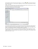
Examine the view displayed in the sheet.
This sheet contains an external reference to the 02 Floor Plan view. After the sheet was added to the project, the
02 Floor Plan view was dragged onto a paper space layout in the A102 02 Floor Plan sheet. When you drag a model
space view from the Project Navigator onto a paper space layout in a sheet, the following actions take place:
■
The view drawing is externally referenced into the plot sheet drawing’s model space.
■
A viewport is created on the current layout, scaled according to the settings held in the model space view’s
properties.
24
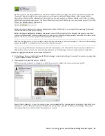
Examine the overall building dimensions.
The dimensions in this drawing were added to the view. Optionally, you could add annotation, such as schedule
tags and tables, dimensions, and title marks to the plot sheet. Whether to create annotation on plot sheets or in
views is a decision you should make based on your workflow and individual needs. For example, using callout
tools creates a workflow in which annotation, tags, and titles are placed in views.
25
On the File menu, click Close to close the sheet, and click No when prompted to save the drawing.
26
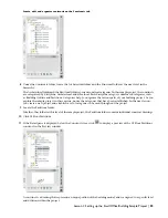
In the Project Navigator title bar, click
to close the Project Navigator.
In this exercise, you explored the Small Office Building Sample Project, while being introduced to the terms and concepts
that are essential to working within a project environment. Using the Project Browser, you accessed the Small Office
Building Sample Project, and selected it as the project environment in which to work. In the Project Navigator, you
viewed the organization and contents of the default project categories: Constructs, Elements, Views, and Sheets. The
relationships among these project components can be summarized as follows: Within a project, elements are referenced
into constructs, constructs are referenced into views, and views are referenced into sheets.
Exercise 2: Creating a Set of Project Tools
In Autodesk
®
Architectural Desktop, you can use tools to add architectural objects, annotation, and documentation
to your drawings. The tools are organized on tool palettes, which are groups of tools that support particular tasks or
processes. For example, the Walls tool palette contains tools for several commonly-used interior and exterior wall styles,
while the Documentation tool palette contains tools for working with schedules and areas. To use a tool, simply click
the tool on the palette and begin drawing in the drawing area.
When you install the software, several tool palettes are provided. You can begin using these default tools right away.
You can modify the tools on these palettes, or create new tools and palettes to meet your project-specific needs.
Lesson 1: Setting up the Small Office Building Sample Project | 37


