7
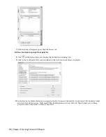
Under Catalog, click Browse.
8
In the Browse for Folder dialog box, navigate to the my documents/autodesk/my projects/small office building folder
and click OK.
9
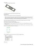
Under Content Source, select Create from drawing.
10
Under Content Source, click Browse.
11
In the Browse drawings in folder for styles dialog box, navigate to the my documents/autodesk/my projects/small office
building/standards/object styles folder, select Styles_STD.dwg, and click Open.
12
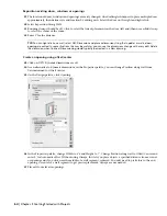
Under Tool Organization, select Group tools by object type and Create tools in Palettes.
13
Under Create tools for the following objects, verify that all of the objects are selected.
14
Click OK. Tools are created for you automatically and much more quickly than creating tools manually.
15
On the Project Navigator, click Content Browser. This icon is for the project-specific content browser library.
If your new catalog is not displayed in the Content Browser main window yet, follow the next two steps to add it
to your user library.
16
In the left pane of the Content Browser, right-click, and click Add Catalog.
17
In the Add Catalog dialog box, select Add an existing catalog or web site, and browse to the catalog (ATC) you
created in the previous steps. The catalog is in the project folder. Then, click OK.
The new catalog is appended to the list of catalogs in the Content Browser. Tools can be dragged as needed from
the library to your project palette.
18
Close Content Browser.
Exercise 5: Defining Building Levels
After you have created and selected the current project environment in the Project Browser, you work in the Project
Navigator to create and document your building model. You begin by defining the building’s vertical segments, or
levels. This exercise shows how to use the Project Navigator to define the number of levels, their floor-to-floor heights,
and their floor elevations.
Each construct in a building model is assigned to one or more levels. When you assemble a multi-level view from these
constructs, the level assignment for each referenced construct is used as the Z coordinate insertion point for the construct.
For example, when creating multi-level views, each construct is referenced at its level height.
54 | Chapter 2 Getting Started with Projects


