3
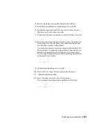
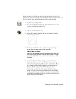
Click the button with the wire coming in from the left.
4
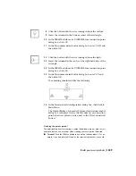
Insert the terminal in the center of the left-hand side of the
rectangle as shown.
TIP
Always use an AutoCAD Snap to insert the wire connection
point.
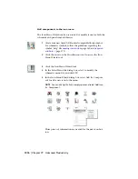
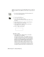
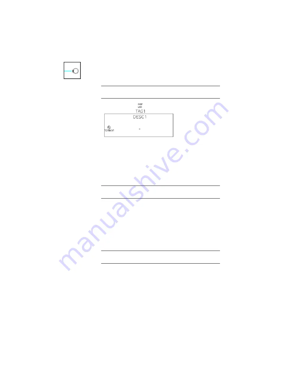
Once you select the wire connection point, you can insert a
terminal attribute and assign a default pin number to the at-
tribute. The TERM01 attribute
➤
X?TERM01 wire connection
point dialog box displays. The terminal number TERMxx at-
tribute text can be linked to a wire connection point X?TERM
attribute. This is done by a match on the last two characters
of the TERMxx and the X?TERMxx attribute names.
NOTE
The "xx" in TERMxx is an incrementing number based
upon how many terminal attributes have been added.
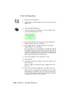
Use this dialog box to move the TERM01 text, change the text
height or justification, convert existing text entity to TERM-
DESC01 or TERM01 attribute, and indicate that there shouldn't
be a TERM text entity for the wire connection.
5
If the TERM01 text is not where you want it, click Move and
select the new location for the text.
TIP
You may have to move the dialog out of the way to see where
the terminal insertion was originally placed.
6
Click OK.
7
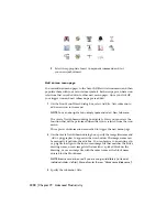
In the Pin number default value dialog box, enter "L1" and
then click OK.
Build your own symbols | 1227
Summary of Contents for 22505-051400-9000 - AutoCAD Electrical 2008
Page 1: ...AutoCAD Electrical 2008 User s Guide February 20 2007 ...
Page 4: ...1 2 3 4 5 6 7 8 9 10 ...
Page 106: ...94 ...
Page 228: ...216 ...
Page 242: ...HP W TERM_ VDC SPECIAL SPACINGFACTOR 0 5 HP WA D TERM_ 02 230 Chapter 5 PLC ...
Page 294: ...282 ...
Page 564: ...552 ...
Page 698: ...686 ...
Page 740: ...728 ...
Page 814: ...802 ...
Page 1032: ...1020 ...
Page 1134: ...1122 ...
Page 1168: ...1156 ...
Page 1177: ...Insert P ID Component Overview of pneumatic tools 1165 ...
Page 1198: ...1186 ...
Page 1269: ...AutoCAD Electrical Command In this chapter AutoCAD Electrical Commands 20 1257 ...
Page 1304: ...Z zip utility 82 1292 Index ...

