where "?" is the style number. An easy way to create a new style is to copy an
existing style's symbols to one of the unused style numbers (6, 7, 8, or 9) and
edit each library symbol.
Scale
Specifies the scale for the PLC module. You can also specify to apply a border
to the PLC module upon insertion.
Module layout
Access:
Click the Insert PLC (Parametric) tool. Select the PLC module to insert, click OK,
and place the PLC in the drawing.
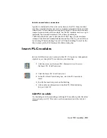
From the Components menu, select Insert PLC Modules
➤
Insert PLC (Para-
metric). Select the PLC module to insert, click OK, and place the PLC in the
drawing.
Spacing
Specifies the spacing for the module. The module will default to the underlying
rung spacing. If you wish to override this spacing, modify the number shown
in the spacing edit box. The arrows below this box increment the number by
the rung spacing. For example, if the rung spacing is 0.5 then each time you
click on ">" the number increases by 0.5.
I/O points
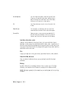
Specifies whether to include all of the points or break the module into many
pieces. You can break a module into as many pieces as you want at insertion
time. This is useful for a module that won't fit into a single ladder column.
You can also add extra space between adjacent I/O points. This allows for the
extra room needed for parallel components. Select Allow Spacers/Breaks and
after each I/O you have the opportunity to insert a space, break the module,
or insert the rest normally. If the module's definition (in the Attributes column
of the Module Terminal Information table of the ace_plc.mdb file or by
selecting the check box in the Break After column of the PLC Database File
Editor dialog box) carries a ";\SPECIAL=BREAK" flag, then the Note highlights
and the module automatically prompts you for permission to break at the
correct point during module insertion.
220 | Chapter 5 PLC
Summary of Contents for 22505-051400-9000 - AutoCAD Electrical 2008
Page 1: ...AutoCAD Electrical 2008 User s Guide February 20 2007 ...
Page 4: ...1 2 3 4 5 6 7 8 9 10 ...
Page 106: ...94 ...
Page 228: ...216 ...
Page 242: ...HP W TERM_ VDC SPECIAL SPACINGFACTOR 0 5 HP WA D TERM_ 02 230 Chapter 5 PLC ...
Page 294: ...282 ...
Page 564: ...552 ...
Page 698: ...686 ...
Page 740: ...728 ...
Page 814: ...802 ...
Page 1032: ...1020 ...
Page 1134: ...1122 ...
Page 1168: ...1156 ...
Page 1177: ...Insert P ID Component Overview of pneumatic tools 1165 ...
Page 1198: ...1186 ...
Page 1269: ...AutoCAD Electrical Command In this chapter AutoCAD Electrical Commands 20 1257 ...
Page 1304: ...Z zip utility 82 1292 Index ...

