Use this tool to insert the X-Y grid labels for drawings that use X-Y Grid for
the Format Referencing. You can also change other settings from here (such
as origin) instead of going back into the Drawing Properties dialog box.
NOTE
Your drawing must be configured for X-Y Grids. Set the Format Referencing
in the Drawing Properties
➤
Drawing Format dialog box to X-Y Grid.
Access:
Click the arrow on the Insert Ladder tool to access the XY Grid tool.
NOTE
You can also access this dialog from the Project Properties or Drawing
Properties dialog boxes. Some options are not available when you access the dialog
box through the properties dialog boxes.
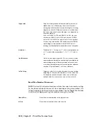
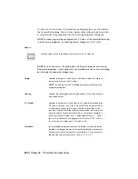
Specifies the origin for the XY grid. Click pick to select the origin on
the drawing or enter X and Y values.
Origin
NOTE
The Pick button is not available when accessed through the
properties dialog box.
Specifies the spacing between the grid columns. Enter the horizontal
and vertical values.
Spacing
Specifies the order that is used from the X-Y grid in determining the
%N part of the tag. If this is set to Horizontal, the horizontal values
X-Y Format
of the grid are used as the first part, and the vertical value as the
second. If Vertical is selected then the vertical values are used for the
first part and the horizontal values used for the second. Example: if
you have Horizontal values of A - F and Vertical values of 1 - 9 and
this is set to Horizontal, you might get a %N value of "B2"; if this is
set to Vertical you might get a %N value of "2B."
(only available when accessed from the toolbar or menu) Specifies
the labels for the grid columns. Enter the horizontal and vertical values.
Grid labels
You can enter the first value only or a complete list. If you enter a list,
separate the values with commas - such as "A, B, C, D."
524 | Chapter 8 Wire/Wire Number Tools
Summary of Contents for 22505-051400-9000 - AutoCAD Electrical 2008
Page 1: ...AutoCAD Electrical 2008 User s Guide February 20 2007 ...
Page 4: ...1 2 3 4 5 6 7 8 9 10 ...
Page 106: ...94 ...
Page 228: ...216 ...
Page 242: ...HP W TERM_ VDC SPECIAL SPACINGFACTOR 0 5 HP WA D TERM_ 02 230 Chapter 5 PLC ...
Page 294: ...282 ...
Page 564: ...552 ...
Page 698: ...686 ...
Page 740: ...728 ...
Page 814: ...802 ...
Page 1032: ...1020 ...
Page 1134: ...1122 ...
Page 1168: ...1156 ...
Page 1177: ...Insert P ID Component Overview of pneumatic tools 1165 ...
Page 1198: ...1186 ...
Page 1269: ...AutoCAD Electrical Command In this chapter AutoCAD Electrical Commands 20 1257 ...
Page 1304: ...Z zip utility 82 1292 Index ...

