NOTE
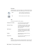
This tool terminates if the bend attempts to connect two different wire
networks or if the bend bypasses more than a single right-angle turn.
1
Click the arrow on the Insert Wires tool to access the Bend
Wire tool.
2
Click the Bend Wire tool.
3
Select one of the two wires that make up a right-angle turn.
4
Select the opposing wire that makes up the right-angle turn.
The additional wire segments are added based on the right-
angle direction.
5
Right-click to exit the command.
Insert multiple bus wiring
1
Click the arrow on the Insert Wires tool to access the Multiple
Wire Bus tool.
2
Click the Multiple Wire Bus tool.
3
Set the horizontal and vertical spacing for the wires.
4
Select the mode for defining the "starting at" position.
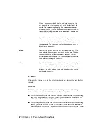
Starting at component wire connection points:
Select the radio
button and click OK. Select or window-select the wire connection
points on the component.
■
■
Starting from another bus:
Select the number of wires (using the
buttons or type in the edit box) and click OK. Specify the connection
point on the existing wire bus for the first wire of the new bus. Slowly
move the cursor over the other existing wires of the bus to allow the
new bus wires to connect.
660 | Chapter 10 Point-to-Point Wiring Tools
Summary of Contents for 22505-051400-9000 - AutoCAD Electrical 2008
Page 1: ...AutoCAD Electrical 2008 User s Guide February 20 2007 ...
Page 4: ...1 2 3 4 5 6 7 8 9 10 ...
Page 106: ...94 ...
Page 228: ...216 ...
Page 242: ...HP W TERM_ VDC SPECIAL SPACINGFACTOR 0 5 HP WA D TERM_ 02 230 Chapter 5 PLC ...
Page 294: ...282 ...
Page 564: ...552 ...
Page 698: ...686 ...
Page 740: ...728 ...
Page 814: ...802 ...
Page 1032: ...1020 ...
Page 1134: ...1122 ...
Page 1168: ...1156 ...
Page 1177: ...Insert P ID Component Overview of pneumatic tools 1165 ...
Page 1198: ...1186 ...
Page 1269: ...AutoCAD Electrical Command In this chapter AutoCAD Electrical Commands 20 1257 ...
Page 1304: ...Z zip utility 82 1292 Index ...


