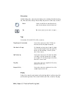
will be displayed, whether the connector goes in vertically or horizontally,
and whether the pins are visible.
Specifies whether the connector comes into the drawing vertically or
horizontally relative to other connectors and the drawing border.
Connector
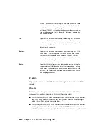
Specifies which direction the plug portion of the connector comes in
relative to the overall plug/receptacle parametric build. The plug
representation is displayed with rounded corners.
Plug
Options include vertical with the plug to the left, vertical with the
plug to the right, horizontal with the plug to the bottom, or horizontal
with the plug to the top.
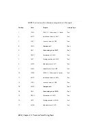
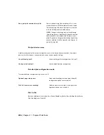
Specifies which pin numbers are visible or hidden on the connector.
Options include showing both sides, showing the plug only, showing
the receptacle only, or hiding both.
Pins
If you select to make the pins on the plug or receptacle invisible, the
attribute and its value are still defined in the block definition on the
drawing file.
If you selected Plug Only or Receptacle Only for the Type, the pin
display options are show or hide only. These show or hide the pin
numbers on a single plug or receptacle symbol.
Size
Defines the outside shell size for the connector. The values in the edit boxes
build the graphical shell that represents the connector on the point to point
diagram.
Specifies the overall thickness of the receptacle side of the con-
nector. This value can be the same as the plug side.
Receptacle
When the connector is built, the receptacle side wire connection
attribute is moved from the insertion point on the divider line to
the outside line representing the receptacle. The associated ter-
minal pin attribute (TERM01_) travels half the distance as the
wire connection attribute placing itself in the middle between
the dimension on the divider line.
Specifies the overall thickness of the plug side of the connector.
This value can be the same as the receptacle side.
Plug
682 | Chapter 10 Point-to-Point Wiring Tools
Summary of Contents for 22505-051400-9000 - AutoCAD Electrical 2008
Page 1: ...AutoCAD Electrical 2008 User s Guide February 20 2007 ...
Page 4: ...1 2 3 4 5 6 7 8 9 10 ...
Page 106: ...94 ...
Page 228: ...216 ...
Page 242: ...HP W TERM_ VDC SPECIAL SPACINGFACTOR 0 5 HP WA D TERM_ 02 230 Chapter 5 PLC ...
Page 294: ...282 ...
Page 564: ...552 ...
Page 698: ...686 ...
Page 740: ...728 ...
Page 814: ...802 ...
Page 1032: ...1020 ...
Page 1134: ...1122 ...
Page 1168: ...1156 ...
Page 1177: ...Insert P ID Component Overview of pneumatic tools 1165 ...
Page 1198: ...1186 ...
Page 1269: ...AutoCAD Electrical Command In this chapter AutoCAD Electrical Commands 20 1257 ...
Page 1304: ...Z zip utility 82 1292 Index ...


